toshiba air conditioner manual

Understanding your Toshiba air conditioner requires the right documentation; manuals offer crucial insights into operation‚ maintenance‚ and troubleshooting for optimal performance and longevity.

Accessing these guides ensures safe and efficient use‚ maximizing the benefits of your cooling system‚ as highlighted by Consumer Reports testing programs.

Importance of the Manual

The Toshiba air conditioner manual is paramount for unlocking the full potential of your unit‚ extending its lifespan‚ and ensuring safe operation. It provides detailed instructions‚ going beyond basic power on/off procedures‚ covering advanced features like timer settings‚ Eco Mode‚ and airflow direction control.

Ignoring the manual can lead to inefficient operation‚ potentially shortening the unit’s life or causing unnecessary repairs. Understanding error codes‚ as detailed within‚ allows for swift troubleshooting‚ potentially avoiding costly service calls.

Furthermore‚ the manual outlines essential safety precautions‚ including electrical safety and proper ventilation‚ safeguarding both the user and the appliance. It’s a vital resource for identifying key components and understanding warranty coverage details‚ ensuring you can fully utilize your investment.

Where to Find Your Toshiba Air Conditioner Manual

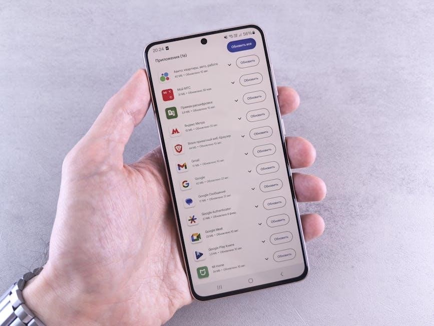
Locating your Toshiba air conditioner manual is often straightforward. Begin by checking the documentation included with the unit upon purchase – a physical copy is frequently provided. If misplaced‚ the Toshiba Appliances support website is a primary resource‚ offering downloadable manuals based on your specific model number.

Alternatively‚ searching online using the full model number (e.g.‚ RAC-WK1212ESCWRU) will yield results from Toshiba and authorized distributors.

For assistance‚ contacting Toshiba support directly‚ providing the product serial number and category (air conditioner)‚ can facilitate manual delivery. Specialist partners‚ like Air-Cond International GmbH‚ may also offer access to documentation or guidance in locating the correct manual for your appliance.

Understanding Your Toshiba Air Conditioner Model

Identifying your Toshiba AC’s model and serial number is key to accessing specific documentation‚ parts‚ and support resources for optimal performance and maintenance.

Locating the Model Number

Finding the model number on your Toshiba air conditioner is the first step towards accessing relevant manuals and support. Typically‚ this identifier is located on a sticker affixed to the unit itself. For indoor units‚ check near electrical covers or on the underside of the appliance.

Outdoor units generally display the model number on the chassis‚ either at the front or side. This alphanumeric code is crucial for accurate identification when searching for documentation or replacement parts. Remember‚ knowing your specific model ensures you receive the correct information for your Toshiba air conditioner‚ as highlighted in various repair guides and online resources.

Refer to videos demonstrating location techniques for further assistance.

Decoding the Serial Number

The Toshiba air conditioner serial number‚ often found alongside the model number‚ provides valuable information about the unit’s production date and origin. While not globally unique‚ it aids in tracking manufacturing details and warranty eligibility. Unfortunately‚ directly decoding the serial number to pinpoint the exact production year can be challenging without specific Toshiba documentation.

Many users have sought assistance online to decipher their serial numbers‚ highlighting the difficulty in self-interpretation. Contacting Toshiba support directly is often the most reliable method for obtaining precise production information based on the serial number. This information is vital when registering your product or claiming warranty services.

Remember to have your serial number readily available when contacting support.

Identifying Key Components

Toshiba air conditioner components vary by model‚ but common elements include the indoor and outdoor units‚ air filters‚ coils‚ compressor‚ and control panel. The indoor unit houses the evaporator coil and fan‚ distributing cooled or heated air. The outdoor unit contains the compressor and condenser coil‚ releasing heat.

Locating these parts is crucial for maintenance. Air filters are typically found behind a removable panel on the indoor unit. Coils require periodic cleaning‚ and their access points are detailed in the manual. Electrical covers‚ often on the underside or side‚ house vital components.

Understanding component locations aids in troubleshooting and part replacement‚ ensuring efficient operation.

Basic Operation and Features

Toshiba ACs offer simple controls: power on/off‚ mode selection (cool‚ heat‚ dry‚ auto)‚ fan speed adjustment‚ and precise temperature settings for comfort.

Powering On and Off

Initiating operation typically involves pressing the power button on the unit itself or via the remote control; a clear indicator light confirms activation. Ensure the unit is properly plugged into a functioning electrical outlet‚ observing all electrical safety precautions detailed in the manual.

To deactivate‚ simply press the power button again; the indicator light should extinguish. Some models feature a standby mode‚ consuming minimal energy while retaining settings. Always disconnect the power during extended periods of non-use or before performing maintenance‚ like cleaning filters or coils‚ to prevent electrical hazards. Refer to your specific model’s manual for detailed instructions and safety guidelines regarding powering the unit on and off‚ as procedures can vary slightly.

Mode Selection (Cool‚ Heat‚ Dry‚ Auto)

Toshiba air conditioners offer versatile modes to suit diverse climate control needs. Cool mode lowers the room temperature‚ ideal for warm weather. Heat mode provides warmth during colder seasons‚ utilizing the unit’s heating capabilities. Dry mode reduces humidity‚ creating a more comfortable environment‚ particularly in damp climates.

Auto mode intelligently adjusts cooling and heating based on the room’s temperature‚ optimizing energy efficiency. Selecting a mode is typically done via the remote control‚ with clear icons indicating each function. Consult your manual for specific instructions on mode selection and recommended usage scenarios‚ ensuring optimal performance and comfort. Understanding these modes maximizes your air conditioner’s functionality.

Fan Speed Control

Toshiba air conditioners provide adjustable fan speeds for personalized comfort and energy management. Typically‚ options include Auto‚ Low‚ Medium‚ and High. Auto mode automatically adjusts fan speed based on temperature settings. Lower speeds conserve energy and minimize noise‚ suitable for quiet environments or maintaining a consistent temperature.

Higher speeds deliver rapid cooling or heating‚ ideal for quickly adjusting room temperature. Fan speed is usually controlled via the remote control‚ with intuitive buttons for easy adjustment. Refer to your specific model’s manual for detailed instructions and to understand the impact of each speed setting on airflow and energy consumption‚ optimizing your comfort.

Temperature Adjustment

Toshiba air conditioners allow precise temperature control for optimal comfort. Utilizing the remote control‚ you can easily increase or decrease the set temperature‚ typically displayed in Celsius or Fahrenheit. The temperature range varies by model‚ but generally spans from 16°C to 30°C (61°F to 86°F).

Adjustments are often made in one-degree increments‚ providing granular control. Consider using Auto mode‚ which automatically maintains the desired temperature. Refer to your manual for specific temperature limits and features like “Comfort Sleep” which subtly adjusts temperature during the night. Proper temperature settings contribute to energy efficiency and personalized comfort.

Advanced Features and Settings

Toshiba air conditioners boast features like timers‚ sleep mode‚ and eco mode‚ enhancing user experience and energy savings‚ as detailed in product specifications.

Timer Function

The timer function on your Toshiba air conditioner allows for automated operation‚ enhancing convenience and potentially reducing energy consumption. You can typically set a timer to start the unit at a specific time‚ pre-cooling or pre-heating your space before your arrival.

Conversely‚ a timer can be programmed to stop the unit after a set duration‚ preventing unnecessary operation while you sleep or are away. This feature is particularly useful for optimizing energy usage and maintaining a comfortable environment without constant manual adjustments.

Refer to your specific model’s manual for detailed instructions on programming the timer‚ as the interface and options may vary. Some models offer multiple timer settings for greater flexibility.

Sleep Mode

Sleep mode on a Toshiba air conditioner is designed to create a more comfortable sleeping environment by gradually adjusting the temperature throughout the night. Typically‚ this involves a slight increase in temperature during cooling mode‚ or a slight decrease during heating‚ preventing overcooling or overheating while you sleep.

This feature often includes a programmed schedule that mimics natural temperature fluctuations‚ promoting better sleep quality. It also tends to reduce fan speed to minimize noise‚ ensuring a peaceful atmosphere.

Consult your Toshiba air conditioner’s manual for specific sleep mode settings and customization options‚ as these can vary between models. Utilizing sleep mode can contribute to energy savings as well.

Eco Mode

Eco Mode on your Toshiba air conditioner is a smart energy-saving function designed to reduce power consumption while maintaining a comfortable room temperature. This mode intelligently optimizes cooling or heating performance by adjusting fan speeds and compressor operation.

Typically‚ Eco Mode prevents excessive cooling by avoiding extremely low temperatures‚ and it minimizes energy waste without significantly compromising comfort. It’s an excellent choice for everyday use‚ especially when the room isn’t occupied for extended periods.

Refer to your specific Toshiba air conditioner manual to understand how Eco Mode functions on your model and any available customization options. Embracing Eco Mode supports environmental responsibility.

Airflow Direction Control

Airflow Direction Control allows you to customize how air is circulated within the room using your Toshiba air conditioner. This feature typically involves adjusting horizontal and vertical louvers or vanes to direct airflow upwards‚ downwards‚ or across the room.

Precise control ensures optimal comfort by preventing direct drafts and evenly distributing cool or warm air. Some models offer automatic swing functions‚ while others allow for fixed positioning of the louvers.

Consult your Toshiba air conditioner manual for specific instructions on operating the airflow direction controls‚ as the interface may vary between models. Proper airflow management enhances efficiency and personal comfort.

Maintenance and Troubleshooting

Regular maintenance‚ like filter cleaning‚ is vital for optimal performance. Troubleshooting guides within your Toshiba manual address common issues and error codes efficiently.

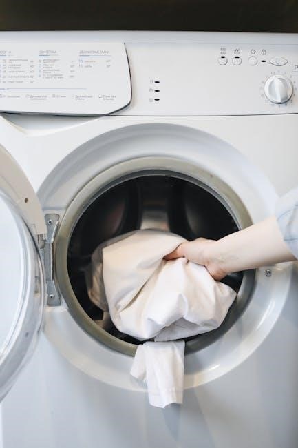
Cleaning the Air Filters

Maintaining clean air filters is paramount for efficient operation and air quality; Your Toshiba air conditioner manual will detail the specific filter location within your model. Generally‚ filters are found behind the front panel‚ easily accessible for removal.

Regularly – typically every two to four weeks – remove the filters and gently wash them with mild detergent and water. Ensure they are completely dry before reinstalling to prevent mold growth. A clogged filter restricts airflow‚ reducing cooling efficiency and potentially causing the unit to work harder‚ leading to increased energy consumption and potential damage.

Refer to your manual for detailed instructions and diagrams specific to your Toshiba model‚ as filter types and cleaning procedures can vary. Consistent filter cleaning contributes significantly to the longevity and performance of your air conditioning system.

Cleaning the Coils

Maintaining clean condenser and evaporator coils is crucial for optimal cooling performance; Your Toshiba air conditioner manual provides specific guidance‚ but generally involves disconnecting power before starting. The outdoor unit’s condenser coils accumulate dirt and debris‚ hindering heat dissipation.

Use a fin comb to straighten bent fins‚ then gently clean the coils with a soft brush or vacuum attachment. Avoid high-pressure water‚ which can damage the delicate fins. The evaporator coils‚ located inside the unit‚ also require periodic cleaning to ensure efficient cooling.

Professional cleaning is recommended annually for thorough coil maintenance. Dirty coils force the unit to work harder‚ increasing energy consumption and potentially leading to compressor failure. Refer to your manual for detailed instructions and safety precautions.

Troubleshooting Common Issues

Your Toshiba air conditioner manual is the first resource for resolving common problems. If the unit isn’t cooling‚ check the air filter‚ thermostat settings‚ and power supply. A frozen evaporator coil can occur due to restricted airflow; turn off the unit and allow it to thaw.

Strange noises might indicate a loose component or a failing fan motor. Water leaks could stem from a clogged drain line – clear it carefully. If the unit cycles on and off frequently‚ it may be oversized or have a refrigerant leak.

Consult the error code section of your manual for specific diagnostics. If issues persist‚ contact Toshiba support or a qualified technician for assistance‚ avoiding self-repair that could void the warranty.

Error Codes and Their Meanings

Toshiba air conditioner manuals dedicate sections to decoding error codes displayed on the unit’s control panel. These codes are vital for pinpointing the source of malfunctions‚ enabling efficient troubleshooting. Common codes relate to sensor failures‚ compressor issues‚ or refrigerant leaks.

For example‚ a specific code might indicate a problem with the indoor fan motor‚ while another signals a communication error between the indoor and outdoor units. The manual provides detailed explanations for each code‚ suggesting potential solutions or indicating when professional service is required.

Always refer to your specific model’s manual‚ as error codes vary. Ignoring these signals can lead to further damage and costly repairs‚ so prompt attention is crucial.

Safety Precautions

Prioritize electrical safety and proper ventilation when handling your Toshiba air conditioner; avoid refrigerant exposure‚ and always consult the manual for guidance.

Electrical Safety

Always disconnect the air conditioner from the power source before performing any maintenance or cleaning. Never operate the unit with a damaged power cord or plug‚ and avoid using extension cords whenever possible. If an extension cord is absolutely necessary‚ ensure it has the appropriate amperage rating.

Ensure the electrical outlet is properly grounded to prevent electric shock. Do not touch the unit with wet hands or operate it in damp environments. Inspect the wiring regularly for any signs of damage or wear. Consult a qualified electrician for any electrical repairs or installations‚ adhering to local electrical codes for safe operation and preventing potential hazards.

Proper Ventilation

Maintaining adequate ventilation is crucial for optimal air conditioner performance and indoor air quality. Ensure there are no obstructions blocking the air inlet or outlet vents‚ both indoors and outdoors. Avoid placing furniture or other objects too close to the unit‚ allowing for sufficient airflow around all sides;

Regularly check for and remove any dust or debris that may accumulate around the vents. Proper airflow ensures efficient cooling and prevents the unit from overheating. Good ventilation also helps to distribute cool air evenly throughout the room‚ enhancing comfort and reducing energy consumption‚ contributing to a healthier indoor environment.

Handling Refrigerant

Refrigerant handling requires extreme caution and should only be performed by qualified technicians. Do not attempt to repair or service the refrigerant circuits yourself‚ as this can lead to serious injury or environmental damage. Refrigerant is a hazardous substance and requires specialized equipment and training for safe handling.

Improper handling can result in leaks‚ which are harmful to the environment and can reduce the cooling efficiency of your Toshiba air conditioner. Always contact a certified professional for any refrigerant-related issues‚ ensuring compliance with environmental regulations and maintaining the integrity of your system. Ignoring this precaution poses significant risks.

Parts and Replacement

Locating replacement parts for your Toshiba AC involves identifying the correct part number‚ like TBD62003AFWG‚ and utilizing authorized distributors for compatibility.

Genuine Toshiba parts ensure optimal performance and maintain the warranty‚ avoiding issues with non-approved components.

Finding Replacement Parts

Securing genuine Toshiba replacement parts is crucial for maintaining your air conditioner’s efficiency and longevity. Begin by accurately identifying the specific part needed‚ often requiring the model and serial number of your unit. These numbers‚ typically found on a sticker located on the indoor or outdoor unit‚ are essential for precise matching.

Authorized distributors and the official Toshiba Appliances support website are the most reliable sources. Avoid third-party sellers offering potentially incompatible or substandard components. Websites often list parts with corresponding Toshiba part numbers‚ such as TBD62003AFWG or TBD62083AFG‚ simplifying the selection process.

Consider contacting a specialist partner‚ like those within the Air-Cond International GmbH network‚ for assistance in locating hard-to-find parts or for professional installation. Always prioritize genuine Toshiba parts to uphold the integrity of your system and prevent voiding your warranty.

Toshiba Part Numbers (Examples)

Toshiba utilizes a specific numbering system for its air conditioner components‚ ensuring accurate identification and ordering of replacement parts. These part numbers are critical when sourcing replacements‚ guaranteeing compatibility with your model. Examples include TBD62003AFWG‚ TBD62083AFG‚ and TBD62064AFAG‚ frequently referenced when searching for components.

These alphanumeric codes detail the part’s function and specifications. Understanding the system isn’t always necessary‚ but having the correct number is paramount. Refer to your air conditioner’s parts diagram (often found within the service manual) to pinpoint the exact component and its corresponding number.

Always double-check the part number before ordering‚ as even slight variations can result in an incompatible part. Utilizing authorized Toshiba distributors or referencing official documentation minimizes errors and ensures you receive the correct replacement.

Transistor Array Information

Transistor arrays within a Toshiba air conditioner are vital components‚ often found in the control circuitry managing compressor operation and fan speeds. These arrays act as electronic switches‚ regulating power flow to various system elements. Identifying specific transistor array part numbers‚ like those beginning with ‘TBD’‚ is crucial for repair.

Troubleshooting often involves testing these arrays for functionality; a faulty array can manifest as erratic cooling or complete system failure. Service manuals provide schematics detailing the location and testing procedures for these components.

Replacement requires careful attention to specifications‚ ensuring the new array matches the original in terms of voltage‚ current‚ and pin configuration. Incorrect substitution can lead to further damage or improper operation of the air conditioning unit.

Warranty Information

Toshiba appliances come with warranty coverage; registration is key to validating your product’s benefits. Contact Toshiba support with your product and serial number.

Warranty Coverage

Toshiba air conditioner warranties typically cover defects in materials and workmanship for a specified period‚ often differing based on the model and components. Generally‚ compressors receive extended coverage‚ potentially up to five or even ten years‚ while parts and labor are covered for a shorter duration‚ commonly one year.

Coverage may be voided by improper installation‚ misuse‚ lack of maintenance (like filter cleaning)‚ or unauthorized repairs. It’s crucial to retain proof of purchase and register your product promptly to activate warranty benefits. Carefully review the warranty documentation included with your unit for specific terms‚ conditions‚ and exclusions. Understanding these details ensures you can effectively utilize your warranty should any issues arise during the coverage period.

Registering Your Product

Registering your Toshiba air conditioner is a vital step to ensure seamless warranty service and access to important product updates. This process typically involves providing your product’s serial number‚ purchase date‚ and contact information through the Toshiba Appliances support website or a designated registration portal.

Prompt registration validates your purchase and establishes a record with Toshiba‚ simplifying any future warranty claims. It also allows Toshiba to notify you of relevant safety recalls‚ software updates‚ or promotional offers. Keep your proof of purchase readily available‚ as it may be required during the registration process. Registering demonstrates ownership and streamlines support interactions.

Contacting Toshiba Support

For direct assistance with your Toshiba air conditioner‚ reaching out to Toshiba Support is crucial. The Toshiba Appliances website provides comprehensive contact options‚ including phone numbers and online support forms. Be prepared to provide your product category (air conditioner) and‚ most importantly‚ your product’s serial number for efficient service.

Their support team can assist with troubleshooting‚ warranty inquiries‚ and locating replacement parts. Utilizing the online resources can often resolve common issues quickly. If you require specialized assistance‚ consider contacting a specialist partner within the Air-Cond International GmbH network for localized support and expertise.

Resources and Support

Toshiba offers extensive support through its appliances website‚ a network of specialist partners like Air-Cond International GmbH‚ and readily available online resources.

Toshiba Appliances Support

For direct assistance with your Toshiba air conditioner‚ the official Toshiba Appliances support channel is an invaluable resource. Contacting support allows you to address specific concerns‚ receive guidance on error codes‚ and navigate the intricacies of your model.

When reaching out‚ be prepared to provide your product category (air conditioner) and‚ crucially‚ your product’s serial number. This information enables support representatives to quickly identify your unit and offer tailored solutions.

Toshiba emphasizes customer satisfaction and aims to provide prompt and effective assistance. Their support team can help with everything from basic operational questions to more complex troubleshooting scenarios‚ ensuring you get the most out of your appliance.

Finding a Specialist Partner

Air-Cond International GmbH facilitates access to a robust network of qualified climate professionals specializing in Toshiba air conditioning systems. These specialist partners possess in-depth knowledge of Toshiba products and can provide expert installation‚ maintenance‚ and repair services.

Locating a partner ensures that your air conditioner receives attention from a technician familiar with its specific features and potential issues. This is particularly beneficial for complex repairs or when interpreting error codes detailed in your manual.

The network offers a reliable alternative to DIY solutions‚ guaranteeing quality workmanship and adherence to safety standards. Explore the Air-Cond International GmbH website to find a specialist conveniently located near you.

Air-Cond International GmbH

Air-Cond International GmbH serves as a key resource for Toshiba air conditioning solutions‚ offering a comprehensive suite of services and support. They are instrumental in connecting customers with a network of certified climate professionals for installation and maintenance.

Beyond partner networks‚ Air-Cond International GmbH provides product overviews and career opportunities within the climate control industry. Their website features a dedicated partner login portal‚ streamlining communication and resource access for affiliated technicians.

For direct assistance‚ Air-Cond International GmbH offers a contact channel‚ ensuring customers can readily address inquiries related to Toshiba air conditioning systems and locate appropriate support.

2010 chevrolet malibu owners manual

The 2010 Chevrolet Malibu owners manual provides essential information regarding operation, maintenance, and safety features of your vehicle, ensuring a positive ownership experience.

This comprehensive guide details everything from understanding the vehicle’s identification numbers to performing routine maintenance, like fluid checks and tire care.

Furthermore, it outlines the electrical system, safety features – including airbags and seatbelt usage – and appearance care instructions for both the interior and exterior.

Accessing this manual is crucial for maximizing your Malibu’s performance and longevity, while also promoting safe driving practices and responsible vehicle ownership.

Overview of the Vehicle

The 2010 Chevrolet Malibu represents a significant iteration in the mid-size sedan market, offering a blend of style, comfort, and efficiency. As detailed within the 2010 Chevrolet Malibu owners manual, this vehicle was designed with the driver and passenger experience as a primary focus;

Available in various trims, the Malibu caters to a diverse range of preferences, from standard models to more luxurious configurations. The owners manual highlights key features such as the spacious interior, designed for comfortable seating and ample cargo space. It also emphasizes the vehicle’s commitment to safety, outlining standard and available safety technologies.

Furthermore, the manual provides insight into the Malibu’s engine options, including the efficient L4-2.4L Hybrid variant, and their respective performance characteristics. Understanding these details, as presented in the manual, allows owners to fully appreciate and maintain their vehicle’s capabilities.

The 2010 Malibu aimed to deliver a refined driving experience, and the owners manual serves as a vital resource for unlocking its full potential.

Importance of the Owner’s Manual

The 2010 Chevrolet Malibu owners manual is far more than just a collection of pages; it’s a comprehensive guide to maximizing your vehicle’s lifespan and ensuring a safe, enjoyable driving experience. As highlighted by resources detailing the manual’s contents, it’s the primary source for understanding your Malibu’s specific features and operational nuances.

This manual details critical information regarding maintenance schedules, fluid checks, and tire care – all vital for preventing costly repairs and maintaining optimal performance. It also provides crucial safety information, including proper airbag system function and correct seatbelt usage.

Furthermore, the manual serves as a reference for understanding the electrical system, fuse box locations, and lighting operation. Ignoring the guidance within can lead to improper operation or even damage. Properly utilizing the 2010 Malibu owners manual empowers you to be a proactive and informed vehicle owner, safeguarding your investment and ensuring peace of mind.

Vehicle Identification

The 2010 Chevrolet Malibu owners manual details locating and decoding the Vehicle Identification Number (VIN), alongside certified emission label information for accurate vehicle tracking.

Vehicle Identification Number (VIN) Location

According to the 2010 Chevrolet Malibu owners manual, locating the Vehicle Identification Number (VIN) is crucial for various reasons, including warranty claims, theft recovery, and accurate vehicle history reports.

The primary location for the VIN on your 2010 Malibu is found on a label affixed to the driver’s side dashboard, visible through the windshield. Specifically, it’s positioned on the dashboard’s left-hand side, where it meets the windshield glass.

Additionally, the VIN is also stamped on the vehicle’s frame, typically located within the engine compartment. This location may require some searching and is often found on the driver’s side frame rail. It’s important to note that this stamped VIN may be less easily accessible.

Always refer to your specific owners manual for the most accurate and detailed instructions regarding VIN location, as slight variations may exist depending on the vehicle’s trim level or specific production date.

Decoding the VIN

The 2010 Chevrolet Malibu owners manual doesn’t directly provide a full VIN decoding guide, but understanding its components is valuable; A VIN is a 17-character alphanumeric code uniquely identifying your vehicle.

The first three characters identify the manufacturer (Chevrolet), the next five indicate the vehicle’s make, model, and body style. Characters six through eight denote the engine type and transmission. The ninth character is a security check digit.

The final eight characters represent the vehicle’s serial number, offering a unique identifier within the Chevrolet production line. Online VIN decoders, readily available through automotive websites, can translate these characters into specific vehicle details.

Decoding the VIN allows you to verify vehicle specifications, track its history, and confirm its original equipment, providing valuable information for potential buyers or for your own records.

Certified Emission Label Information

The 2010 Chevrolet Malibu owners manual emphasizes the importance of the vehicle’s certified emission label, typically found under the hood. This label provides crucial information regarding the vehicle’s emission control system compliance.

It details the engine family, emission control information, and whether the vehicle meets California emission standards or federal standards. Understanding this label is vital for maintaining the vehicle’s emission system correctly.

The label also includes information about the evaporative emission control system, ensuring proper fuel vapor management. Tampering with or removing emission control devices is illegal and can result in fines.

Referencing this label during maintenance or repairs ensures that only approved parts and procedures are used, preserving the vehicle’s emission certification and contributing to a cleaner environment.

Operation

The 2010 Chevrolet Malibu owners manual details essential operational procedures, including starting, stopping the engine, and understanding the instrument panel’s indicators and warnings.

Starting and Stopping the Engine

According to the 2010 Chevrolet Malibu owners manual, starting the engine requires ensuring the transmission is in Park or Neutral, and firmly depressing the brake pedal;

Turn the ignition key to the Start position, releasing it once the engine is running; avoid prolonged cranking to prevent starter damage.

For models equipped with a remote start system, consult the manual for specific instructions and safety precautions.

To stop the engine, gently apply the brake pedal and turn the ignition key to the Off position, removing the key to prevent accidental restarts.

The manual emphasizes avoiding turning the key to Off while driving, as this will disable power steering and potentially cause a loss of control.

Always ensure the vehicle is completely stopped before shifting into Park.

Proper engine starting and stopping procedures, as outlined in the manual, contribute to vehicle longevity and safe operation.

Driving Modes (if applicable ‒ Hybrid)

The 2010 Chevrolet Malibu Hybrid owners manual details two primary driving modes: Normal and Eco.

Normal mode prioritizes performance, utilizing both the gasoline engine and electric motor for optimal power delivery in various driving conditions.

Eco mode, conversely, focuses on maximizing fuel efficiency by adjusting throttle response and utilizing the electric motor more frequently.

The manual explains that Eco mode may result in slightly reduced acceleration, but significantly improves gas mileage, particularly during city driving.

A mode indicator on the instrument panel displays the currently selected driving mode.

The system automatically manages the transition between gasoline and electric power, optimizing efficiency without driver intervention.

Understanding and utilizing these modes, as described in the manual, allows drivers to tailor the vehicle’s performance to their specific needs and preferences.

Instrument Panel Overview

The 2010 Chevrolet Malibu owners manual provides a detailed explanation of the instrument panel’s various indicators and gauges.

Key features include the speedometer, tachometer, fuel level gauge, and engine temperature gauge, all clearly displayed for easy monitoring.

Warning lights alert the driver to potential issues, such as low oil pressure, check engine status, or airbag system malfunctions.

The manual emphasizes the importance of understanding these warning lights and promptly addressing any indicated problems.

Additionally, the instrument panel displays information related to the hybrid system, including battery charge level and electric motor operation.

A Driver Information Center (DIC) provides customizable displays for trip data, fuel economy, and other vehicle settings.

Familiarizing yourself with the instrument panel, as outlined in the manual, is crucial for safe and informed driving.

Maintenance

The 2010 Chevrolet Malibu owners manual details a recommended maintenance schedule, fluid checks, tire care, and replacement procedures for optimal vehicle performance.

Recommended Maintenance Schedule

The 2010 Chevrolet Malibu owners manual outlines a crucial maintenance schedule to ensure longevity and reliability. Regular inspections are vital, covering items like engine oil and filter changes – typically every 5,000 miles or six months, whichever comes first – using the specified oil grade.

The manual also details periodic checks of all fluid levels, including coolant, brake fluid, power steering fluid, and transmission fluid. Tire rotation is recommended every 7,500 miles to promote even wear. Further scheduled services include inspecting belts and hoses, air filter replacement, and spark plug replacement at specified intervals.

Adhering to this schedule, as detailed in the manual, helps prevent unexpected breakdowns, maintains optimal fuel efficiency, and safeguards your investment in the vehicle. Ignoring these recommendations can lead to costly repairs down the road.

Fluid Checks and Replacements

The 2010 Chevrolet Malibu owners manual emphasizes the importance of regular fluid checks and replacements for optimal vehicle performance. Engine oil should be checked monthly and replaced according to the recommended schedule, utilizing the correct viscosity grade specified within the manual.

Coolant levels must be maintained to prevent overheating, and the manual details the proper coolant type for your Malibu. Brake fluid should be inspected regularly for contamination and replaced as needed, ensuring effective braking. Power steering fluid levels also require periodic checks, and transmission fluid should be serviced at the intervals outlined in the manual.

Proper fluid maintenance contributes significantly to the longevity of your vehicle’s components and ensures safe, reliable operation. Refer to the manual for specific fluid capacities and replacement procedures.

Tire Information

The 2010 Chevrolet Malibu owners manual provides crucial details regarding tire maintenance and safety. Maintaining proper tire pressure, as indicated on the tire placard (usually located on the driver’s side doorjamb), is essential for optimal handling, fuel efficiency, and tire longevity.

The manual specifies the correct tire size for your Malibu model, ensuring compatibility and performance. Regular tire inspections are vital to identify signs of wear, damage, or uneven tread patterns. Rotate tires according to the recommended schedule to promote even wear and extend their lifespan.

Understanding tire wear indicators and knowing when to replace tires is critical for safe driving. The manual outlines proper tire replacement procedures and emphasizes the importance of using tires that meet the vehicle’s specifications.

Tire Size and Pressure

The 2010 Chevrolet Malibu owners manual details the specific tire size recommended for your vehicle, typically found on the tire information placard. Correct tire size ensures optimal performance, handling, and safety. Common sizes may include 225/50R17 or 235/45R18, but always verify with your vehicle’s placard.

Maintaining proper tire pressure is equally crucial. The manual specifies the recommended cold tire pressure (in PSI) for both front and rear tires. Underinflation can lead to reduced fuel efficiency, increased wear, and compromised handling, while overinflation can result in a harsh ride and uneven wear.

Regularly check tire pressure using a reliable gauge, especially during temperature changes. The manual emphasizes checking pressure when tires are cold, before driving, for accurate readings.

Tire Wear and Replacement

The 2010 Chevrolet Malibu owners manual highlights the importance of regularly inspecting tires for wear and damage. Uneven wear patterns – such as wear on the edges or in the center – can indicate alignment issues, improper inflation, or suspension problems requiring attention.

The manual details tread wear indicators (TWI) molded into the tire grooves. When tread depth reaches the level of these indicators, it’s time for tire replacement. Driving with worn tires significantly reduces traction, especially in wet or snowy conditions, compromising safety.

The manual also advises checking for cuts, bulges, or other damage. Damaged tires should be replaced immediately. When replacing tires, it’s recommended to replace them in pairs or all four to maintain balanced handling and braking performance.

Appearance Care

The 2010 Chevrolet Malibu owners manual provides detailed guidance on maintaining the vehicle’s appearance, covering both exterior cleaning and interior detailing procedures.

Exterior Cleaning and Washing

The 2010 Chevrolet Malibu owners manual emphasizes the importance of regular washing to protect the vehicle’s paint and finish. Begin by rinsing the entire vehicle with cool, clean water to remove loose dirt and debris.

Use a mild automotive soap specifically designed for vehicle finishes, and apply with a soft wash mitt or sponge, working from the top down.

Avoid harsh detergents or abrasive cleaners, as these can damage the paint.

Rinse thoroughly, ensuring all soap residue is removed, and then dry with a clean, soft microfiber towel to prevent water spots.

Pay attention to areas prone to dirt accumulation, such as the lower body panels and wheel wells.

For optimal protection, consider applying a quality wax or sealant after washing, following the product’s instructions carefully.

Regular cleaning helps maintain the Malibu’s aesthetic appeal and prevents long-term damage.

Interior Cleaning and Detailing

The 2010 Chevrolet Malibu owners manual recommends regular interior cleaning to maintain a comfortable and hygienic cabin environment. Begin by removing all loose items and vacuuming carpets, upholstery, and crevices to eliminate dust and debris.

For vinyl and plastic surfaces, use a mild interior cleaner applied to a soft cloth, wiping gently to avoid scratches.

Leather seats require specialized leather cleaner and conditioner to prevent cracking and maintain suppleness.

Clean windows and mirrors with a glass cleaner, ensuring a streak-free finish.

Address stains promptly using appropriate stain removers, testing in an inconspicuous area first.

Pay attention to details like air vents, dashboard seams, and door pockets.

Regular detailing preserves the Malibu’s interior, enhancing its appearance and value, while contributing to a pleasant driving experience.

Electrical System

The 2010 Chevrolet Malibu owners manual details the vehicle’s electrical components, including battery maintenance, fuse box locations, and comprehensive lighting system operation instructions.

Battery Information and Maintenance

The 2010 Chevrolet Malibu owners manual provides crucial details regarding the vehicle’s battery, a vital component of the electrical system. Proper maintenance ensures reliable starting and optimal performance.

The manual outlines the battery’s specifications, including voltage and cold cranking amps (CCA), essential for replacement purposes. It emphasizes the importance of keeping the battery terminals clean and free from corrosion, detailing a safe cleaning procedure.

Furthermore, the manual cautions against leaving lights or accessories on when the engine is off, as this can lead to battery discharge. It also explains the potential impact of extreme temperatures on battery performance and lifespan.

Regarding jump-starting, the manual provides step-by-step instructions, emphasizing safety precautions to prevent damage to the vehicle’s electrical system. It also advises on when to consult a qualified technician for battery testing or replacement, ensuring continued safe operation.

Fuse Box Locations and Diagrams

The 2010 Chevrolet Malibu owners manual dedicates a section to the vehicle’s fuse boxes, critical for protecting the electrical system. It clearly identifies the locations of these fuse boxes, typically found within the passenger compartment and the engine compartment.

Detailed fuse box diagrams are included, illustrating the specific location of each fuse and its corresponding amperage rating. The manual explains how to identify a blown fuse – visually inspecting for a broken filament – and provides instructions for safe replacement.

It stresses the importance of always replacing a blown fuse with one of the identical amperage rating to prevent potential electrical damage or fire hazards. The manual also lists the circuits protected by each fuse, aiding in troubleshooting electrical issues.

Understanding these diagrams and procedures empowers owners to address minor electrical problems independently, while knowing when to seek professional assistance from a qualified technician.

Lighting System Operation

The 2010 Chevrolet Malibu owners manual provides a comprehensive overview of the vehicle’s lighting system, detailing the operation of all interior and exterior lights. It explains the functionality of the headlights – including high and low beams – as well as the turn signals, parking lights, and hazard warning flashers.

The manual clarifies the use of the automatic headlight feature, if equipped, and describes how to adjust headlight aiming for optimal visibility. It also covers the operation of interior lights, such as the dome light, map lights, and trunk light.

Specific instructions are given for using the fog lights, if present, and the manual emphasizes the importance of using lights appropriately to ensure safety and comply with local traffic regulations.

Troubleshooting tips are included for common lighting issues, such as bulb replacement and fuse checks, empowering owners to address minor problems themselves.

Safety Features

The 2010 Chevrolet Malibu owners manual details critical safety systems, including airbags, seatbelt usage guidelines, and proper installation of child safety seats for protection.

Airbag System

The 2010 Chevrolet Malibu owners manual provides detailed information regarding the vehicle’s airbag system, a crucial component of its safety features. This system is designed to work with seatbelts, not replace them, and is engineered to deploy in certain collision scenarios to reduce the risk of serious injury.

The manual explains the locations of the airbags – frontal, side-impact, and potentially curtain airbags – and emphasizes the importance of proper seating positions for optimal protection. It also outlines specific warnings and cautions, such as never placing objects in front of airbags or modifying the airbag system in any way.

Furthermore, the manual details what to expect after an airbag deployment, including the need for system inspection and repair. Understanding the airbag system’s operation and limitations, as described in the manual, is vital for all occupants’ safety.

Always refer to the manual for comprehensive details and specific instructions related to your vehicle’s airbag system.

Seat Belt Usage

The 2010 Chevrolet Malibu owners manual strongly emphasizes the critical importance of proper seat belt usage for all occupants. Seat belts are the primary restraint system in your vehicle and are designed to significantly reduce the risk of injury during a collision.

The manual details how to correctly adjust and wear seat belts, ensuring a snug fit across the hips and shoulder. It also provides specific guidance for different body types and sizes, including instructions for pregnant women. The manual clearly states that all occupants should wear seat belts on every trip, regardless of distance.

Furthermore, it outlines the proper use of seat belts with child safety seats, emphasizing the importance of following all applicable laws and manufacturer’s instructions. Ignoring seat belt safety guidelines can lead to severe injuries or fatalities.

Always consult the manual for complete details and ensure all passengers are properly restrained.

Child Safety Seats

The 2010 Chevrolet Malibu owners manual provides detailed instructions regarding the proper installation and use of child safety seats. It stresses the importance of selecting a seat appropriate for the child’s weight, height, and age, adhering to all local and federal regulations.

The manual illustrates approved seating positions for child restraints within the Malibu, highlighting those equipped with LATCH (Lower Anchors and Tethers for Children) systems; It also explains how to secure seats using seat belts when LATCH isn’t utilized.

Crucially, the manual emphasizes the necessity of reading both the vehicle owner’s manual and the child safety seat’s instruction manual before installation. Incorrect installation can compromise the seat’s effectiveness in a crash.

Always prioritize child passenger safety by following these guidelines meticulously.

chamberlain b4505t installation manual

Chamberlain B4505T Installation: A Comprehensive Guide

This manual provides detailed instructions for installing your Chamberlain B4505T garage door opener, ensuring a smooth and safe setup process for optimal performance.

The Chamberlain B4505T is a ½ horsepower chain drive garage door opener designed for single-car garages. It’s known for its reliable performance and durability, offering a secure and convenient solution for automating your garage door. This opener features a robust motor and a durable chain drive system, providing years of dependable service.

This installation manual will guide you through each step of the process, from verifying package contents to final testing and optional MyQ integration. Proper installation is crucial for safe and efficient operation. We strongly recommend reading this entire manual before beginning the installation to familiarize yourself with the procedures and safety precautions. Enjoy the convenience and security of your new Chamberlain opener!

Safety Precautions & Warnings

Garage door openers involve potentially hazardous moving parts. Always disconnect the power to the garage door opener circuit before performing any installation, maintenance, or repairs. Never allow children to operate the opener or play near the garage door. Ensure the garage door is balanced properly; an unbalanced door can cause serious injury.

Wear appropriate safety glasses during installation to protect your eyes. Be cautious when working with ladders and tools. If you are uncomfortable performing any step of the installation, consult a qualified professional. Failure to follow these safety precautions could result in property damage, personal injury, or even death. Prioritize safety throughout the entire process.

Package Contents Verification

Before beginning installation, carefully unpack the Chamberlain B4505T and verify all components are present. The package should include the motor unit, rail sections, door bracket, safety sensors, remote controls, mounting hardware (bolts, nuts, washers), a chain, and this installation manual.

A parts list is typically included within the manual; cross-reference this list with the actual contents of the box. Do not proceed if any parts are missing. Contact Chamberlain customer support immediately to request replacements. Keeping the original packaging can be helpful for returns or warranty claims. Thorough verification prevents delays during installation.

Identifying All Components

Familiarize yourself with each part of the Chamberlain B4505T system. The motor unit houses the motor and electronics. Rail sections connect to form the track for the carriage. The door bracket attaches to your garage door. Safety sensors prevent the door from closing on obstructions.

Remote controls allow for convenient operation. Mounting hardware secures the unit and rail; The chain connects the carriage to the motor. Carefully examine each item, noting its shape and function. Refer to the diagrams in the installation manual for visual identification. Knowing each component beforehand streamlines the installation process and reduces potential errors.

Checking for Damage During Shipping

Upon receiving your Chamberlain B4505T, thoroughly inspect all packaging for signs of damage; Look for dents, tears, or punctures to the boxes. Carefully open each carton and examine the components inside.

Check for bent rails, cracked motor housing, or damaged remote controls. Note any scratches or missing parts. If damage is present, do not attempt installation. Immediately contact Chamberlain customer support and the shipping carrier to report the issue. Document the damage with photographs for claim purposes. Installing damaged components could compromise safety and void the warranty.

Tools Required for Installation

Before beginning the Chamberlain B4505T installation, gather the necessary tools to ensure a smooth process. You will need a Phillips head screwdriver, a flathead screwdriver, and an adjustable wrench. A step ladder is crucial for reaching the garage ceiling.

A drill with various drill bits will be required for mounting brackets. Safety glasses are essential to protect your eyes from debris. A measuring tape will help with accurate positioning. Consider having a helper available, especially when lifting the motor unit. Having these tools readily available will streamline the installation and minimize delays.

Pre-Installation Checklist

Prior to installing your Chamberlain B4505T, a thorough pre-installation check is vital for a successful outcome. First, disconnect the garage door from its existing opener, if applicable, and manually operate the door to ensure it’s balanced and moves smoothly.

Clear the garage floor of any obstructions. Inspect the garage door tracks for any damage or bends. Confirm you have access to a grounded electrical outlet near the motor location. Review the included diagrams and instructions to familiarize yourself with the components. Completing these steps beforehand will save time and prevent potential issues during installation.

Garage Door Compatibility Assessment

Before proceeding, verify your garage door is compatible with the Chamberlain B4505T opener. This unit is designed for standard sectional doors. Ensure your door isn’t excessively heavy – typically, it should weigh less than 150 pounds.

Check for obstructions that might hinder the door’s movement. Doors with significant warping or damage may require professional repair before installation. Confirm the door operates smoothly with balanced springs. The opener isn’t intended for use with one-piece tilt-up doors or doors with unusual configurations. Compatibility ensures safe and reliable operation.

Ensuring Adequate Space & Clearance

Proper clearance is crucial for safe and efficient operation of the Chamberlain B4505T. Verify at least 2 inches of clearance exists between the garage door and the ceiling when the door is fully open.

Also, ensure there’s a minimum of 7.5 feet of space in front of the door to allow for full door travel. Check for obstructions like shelving or vehicles that could interfere. Adequate side clearance – at least 3 feet on each side of the opener – is also necessary for safe access during maintenance and adjustments. Confirm these dimensions before mounting the unit.

Mounting the Motor Unit

Securely mounting the Chamberlain B4505T motor unit is paramount for stable operation. Begin by locating the pre-drilled mounting holes on the unit itself. Using appropriate lag screws (typically provided), attach a mounting bracket firmly to a ceiling joist or concrete garage ceiling.

Ensure the bracket is level and can support the unit’s weight. Carefully lift the motor unit onto the bracket, aligning the slots. Double-check that all connections are secure before releasing the unit. A properly mounted unit minimizes vibration and ensures long-term reliability.

Installing the Rail System

The rail system transmits power to your garage door; precise installation is crucial. Begin by assembling the rail sections, connecting them securely with the provided hardware. Ensure all joints are aligned and locked into place for smooth operation.

Next, carefully position the assembled rail along the garage ceiling, following the path of your garage door. Secure the rail to ceiling joists using appropriate brackets and screws, maintaining consistent spacing. Proper rail alignment prevents binding and ensures efficient door movement. Double-check all connections for stability.

Rail Assembly Instructions

Begin by laying out all rail sections on a clean, flat surface. Identify the rail sections according to the diagram in your manual – typically a straight section and a curved section. Connect the sections using the provided rail connectors, ensuring they click securely into place.

Tighten all connector bolts with a wrench, but avoid over-tightening, which could damage the rail. Verify the assembled rail is straight and free of kinks or bends. Pay close attention to the orientation of the rail; the curved section should face towards the door. Securely fasten the end caps to the rail ends for a finished look and added safety.

Attaching the Rail to the Motor Unit

Carefully align the assembled rail with the mounting bracket on the motor unit. Insert the rail’s end into the receiver tube on the motor, ensuring a snug fit. Secure the rail using the provided bolts and washers, tightening them firmly with a wrench.

Double-check that the rail is securely fastened and doesn’t wobble. Proper attachment is crucial for smooth and reliable operation. Inspect the connection points for any gaps or loose hardware. Ensure the chain or belt is properly aligned within the rail before proceeding. This step establishes the foundational link between power and movement.

Connecting the Door Bracket & Arm

Attach the L-shaped door bracket securely to the center of your garage door using the supplied lag screws and washers; Ensure it’s level and firmly fastened to withstand the door’s weight and movement. Next, connect the door arm to both the door bracket and the trolley on the rail system.

Use the provided pin and retaining clip to secure the arm connections. Verify that the arm moves freely without binding. Adjust the arm’s length if necessary to achieve a smooth, vertical lift. Proper alignment is vital for efficient operation and prevents strain on the opener.

Limit Switch Adjustment

Proper limit switch adjustment is crucial for preventing over-travel of the garage door, ensuring safe and reliable operation. Locate the upper and lower limit adjustment screws on the motor unit. Turning the screws clockwise decreases travel, while counterclockwise increases it.

Begin by setting the down travel limit, ensuring the door closes completely without excessive force. Then, adjust the up travel limit to allow the door to open to the desired height. Test the limits repeatedly, making small adjustments until the door operates smoothly and stops precisely at the desired positions.

Wiring & Electrical Connections

Before commencing any wiring, absolutely disconnect the power at the circuit breaker. Identify the designated wiring terminals on the motor unit for the power cord connection – typically black to black (hot), white to white (neutral), and green or bare copper to ground.

Securely connect the wires using wire connectors, ensuring a tight and reliable connection. Double-check all connections before restoring power. Never attempt to modify the power cord or plug. If the existing wiring is damaged, consult a qualified electrician. Proper grounding is essential for safety and optimal performance.

Programming the Remote Controls

To program your Chamberlain B4505T remotes, locate the “Learn” button on the motor unit – it’s usually yellow or orange. Press and release the “Learn” button; the indicator light will illuminate. Within 30 seconds, press and hold the desired button on the remote control until the garage door opener light flashes, confirming successful programming.

Repeat this process for each additional remote. If programming fails, ensure the remote batteries are fresh and try again. Some models may require clearing existing codes before adding new ones – consult the full manual for specific instructions. Always test each remote after programming.

Testing the Garage Door Operation

After installation and programming, thoroughly test the garage door’s operation. Use both the remote controls and the wall-mounted button to open and close the door, observing its full range of motion. Pay close attention to ensure smooth, even travel without any jerks or unusual noises.

Test the safety features, including the auto-reverse function. Place a one-inch object in the door’s path and verify the opener reverses direction upon contact. Adjust the force settings if necessary. Finally, confirm the limit switches are correctly set, preventing over-travel. Regular testing ensures continued safe and reliable operation.

Troubleshooting Common Issues

If the door doesn’t open or close, first check the power supply and ensure the outlet is functioning correctly. Verify remote control batteries and reprogram if needed. For auto-reverse issues, examine the safety sensors for obstructions or misalignment – clean the lenses. If the motor hums but the door doesn’t move, the rail may be disconnected or the door spring tension is incorrect.

Consult the manual’s troubleshooting section for specific error codes and solutions. If problems persist, contact Chamberlain’s customer support for assistance. Remember to always disconnect power before attempting any repairs.

Chamberlain MyQ Integration (Optional)

Enhance your garage door control with Chamberlain’s MyQ technology! This optional integration allows you to monitor, open, and close your garage door remotely using your smartphone. Download the MyQ app and follow the in-app instructions to connect your B4505T opener to your home Wi-Fi network.

MyQ offers features like real-time alerts, guest access, and integration with other smart home devices. Ensure a stable Wi-Fi connection during setup. Refer to the MyQ app’s help section or Chamberlain’s website for detailed guidance and troubleshooting tips. Enjoy the convenience and security of smart garage door control!

Warranty Information & Customer Support

Your Chamberlain B4505T garage door opener is backed by a comprehensive warranty, protecting against manufacturing defects. Please retain your proof of purchase for warranty claims. Specific warranty durations vary by component – the motor unit, rail, and accessories each have individual coverage periods.

For assistance, visit Chamberlain’s website or contact their customer support team. You’ll find helpful FAQs, troubleshooting guides, and contact information for phone and email support. Dedicated representatives are available to address your questions and concerns, ensuring a positive ownership experience. Refer to the included warranty documentation for complete details.

honeywell t4 pro installation manual pdf

Honeywell T4 Pro Installation Manual PDF: A Comprehensive Guide

This guide unlocks the potential of your Honeywell T4 Pro system, offering detailed instructions for a seamless setup. Explore user manuals,
technical specifications, and troubleshooting advice. Discover how to navigate the interface and optimize performance for enhanced security and control.

The Honeywell T4 Pro represents a significant advancement in home security technology, offering a robust and versatile system designed for comprehensive protection. This innovative system seamlessly integrates cutting-edge features with user-friendly operation, making it an ideal choice for both homeowners and professional installers.

As highlighted in available resources, the T4 Pro isn’t merely a security panel; it’s a central hub capable of managing a wide array of sensors, detectors, and communication modules; Its core functionality revolves around providing reliable intrusion detection, environmental monitoring (like temperature and carbon monoxide), and smart home integration capabilities.

The availability of a detailed installation manual in PDF format is crucial for ensuring a successful setup. This manual, often referenced in online discussions, serves as a comprehensive guide, walking users through every step of the process – from initial planning and wiring to system programming and testing. Understanding the system’s capabilities and following the manual’s instructions are paramount to maximizing its effectiveness and enjoying peace of mind. The T4 Pro aims to redefine smart home security, and this manual is your key to unlocking its full potential.

Understanding the T4 Pro System Components

The Honeywell T4 Pro system comprises several key components working in harmony to deliver robust security. Central to the system is the control panel itself, the brains of the operation, managing all connected devices and user interactions; A crucial element, detailed within the installation manual PDF, is the system’s compatibility with a diverse range of wireless and hardwired sensors.

These sensors include door and window contacts, motion detectors, glass break detectors, and smoke/carbon monoxide detectors. The manual emphasizes the importance of correctly identifying and connecting these components. Furthermore, the T4 Pro supports various communication modules, enabling remote access and control via smartphone apps like Honeywell Home.

Keypads provide a local interface for arming/disarming the system and accessing settings. The system also integrates with optional sirens and strobe lights for audible and visual alerts. Understanding the function of each component, as clearly outlined in the PDF manual, is vital for proper installation and configuration. Proper component identification and connection are essential for a fully functional and reliable security system.

Safety Precautions Before Installation

Prior to commencing installation of your Honeywell T4 Pro system, strict adherence to safety precautions is paramount. Always disconnect power to the existing security system and any associated wiring at the breaker panel to prevent electrical shock. The installation manual PDF stresses the importance of verifying power is off using a reliable voltage tester.

Exercise caution when working with wiring, ensuring all connections are secure and properly insulated. Avoid installing components in damp or wet locations. If working at heights, utilize a stable ladder and appropriate fall protection. Be mindful of potential hazards like hidden wiring or plumbing within walls.

The manual also advises against installing the control panel in direct sunlight or near heat sources. Wear appropriate personal protective equipment (PPE), including safety glasses and gloves. If you are uncomfortable performing any aspect of the installation, consult a qualified security professional. Ignoring these precautions could result in personal injury or damage to the system. Review the complete safety section within the PDF manual before beginning.

Required Tools and Materials

Successful Honeywell T4 Pro installation necessitates a specific set of tools and materials. The installation manual PDF details a comprehensive list to ensure a smooth process. Essential tools include a screwdriver set (Phillips and flathead), wire strippers, wire connectors (wire nuts or crimp connectors), a drill with various drill bits, and a voltage tester. A multimeter is highly recommended for verifying wiring continuity and voltage levels.

Required materials encompass appropriate gauge wiring (typically 18-22 AWG), mounting screws and anchors, labeling tape for identifying wires, and potentially conduit for protecting wiring runs. Depending on the system configuration, you may also need resistors for end-of-line supervision.

The manual emphasizes the importance of using high-quality materials to ensure system reliability. Ensure all wiring meets local building codes. Having these tools and materials readily available before starting will significantly streamline the installation process and prevent delays. Refer to the PDF for a complete and detailed list tailored to your specific T4 Pro setup.

Step-by-Step Installation Guide ⎼ Wiring

The Honeywell T4 Pro installation manual PDF provides a detailed, step-by-step wiring guide. Begin by disconnecting power to the control panel before commencing any wiring work – safety first! Identify the appropriate terminals on both the control panel and the T4 Pro module. The manual uses clear diagrams to illustrate wire connections.

Wiring typically involves connecting power (typically 24VAC), ground, and communication wires (data lines). Carefully strip the insulation from the wires, ensuring sufficient length for secure connections. Use wire connectors to join the wires, ensuring a tight and reliable connection.

Pay close attention to polarity and wire color coding as indicated in the manual. Incorrect wiring can damage the system or cause malfunctions. Double-check all connections against the wiring diagram before restoring power. The PDF emphasizes proper wire routing and securing to prevent accidental disconnections or damage. Follow the manual’s instructions meticulously for a successful installation.

Connecting to the Control Panel

The Honeywell T4 Pro installation manual PDF details the process of connecting the module to your existing security control panel. Ensure the control panel is compatible with the T4 Pro before proceeding – the manual lists compatible models. Power down the control panel completely before establishing any connections.

Connection is typically achieved via a dedicated communication bus, often utilizing a four-wire connection. The manual provides specific terminal assignments for each wire (data+, data-, power, ground). Carefully insert the wires into the designated terminals on both the T4 Pro and the control panel, ensuring a secure fit.

Refer to the control panel’s manual for specific instructions on enabling the connection and adding the T4 Pro as a device. The Honeywell PDF stresses the importance of verifying the communication link after wiring. Successful connection is usually indicated by a status light on the T4 Pro module. Proper connection is crucial for seamless system integration.

Programming the Honeywell T4 Pro

The Honeywell T4 Pro installation manual PDF provides comprehensive guidance on programming the device through your security control panel. Programming involves defining zone types (entry/exit, interior, perimeter), assigning device numbers, and configuring communication settings. The manual details specific programming codes and sequences for various control panel brands.

Key programming parameters include sensitivity levels, alarm reporting options, and tamper protection settings. Adjusting sensitivity ensures accurate detection while minimizing false alarms. Configure alarm reporting to specify how the system communicates with the monitoring center. The PDF emphasizes the importance of accurate zone programming for effective security.

Advanced programming options allow customization of features like entry/exit delays, cross-zoning, and dual-verification. Refer to the manual’s troubleshooting section if you encounter programming errors. Proper programming is essential for optimal performance and reliable security system operation. Always save your programming changes!

Testing the System After Installation

The Honeywell T4 Pro installation manual PDF stresses the critical importance of thorough system testing post-installation. Begin with a zone-by-zone test, activating each sensor (doors, windows, motion detectors) to verify proper communication with the control panel. Observe the panel’s display to confirm correct zone identification and alarm status.

Next, test the alarm reporting functionality by triggering an alarm and confirming that the signal is received by the monitoring center. The manual details how to initiate a test signal and interpret the response. Verify the siren’s audibility and ensure it functions as expected. Test the system’s communication pathways – both wired and wireless.

Walk-test the motion detectors to confirm their coverage area and sensitivity. The PDF recommends testing under various conditions to identify potential false alarm triggers. Document all test results and address any discrepancies immediately. Comprehensive testing ensures the system operates reliably and provides effective security.

Troubleshooting Common Installation Issues

The Honeywell T4 Pro installation manual PDF dedicates a section to resolving frequent installation challenges. A common issue is wiring errors; the manual provides detailed diagrams and troubleshooting steps to identify and correct incorrect connections. Communication failures between sensors and the panel are also addressed, suggesting checks for signal strength and interference.

If the panel doesn’t power on, the manual guides users through verifying the transformer’s output and battery connections. Programming difficulties are often resolved by referencing the manual’s step-by-step instructions and example configurations. False alarms can stem from improperly positioned sensors or incorrect sensitivity settings – the PDF offers guidance on optimization.

The manual also covers issues related to wireless communication, including pairing problems and signal dropouts. It emphasizes checking antenna placement and avoiding interference sources. Remember to consult the error code section for specific diagnostic information. Systematic troubleshooting, guided by the manual, minimizes downtime and ensures a functional security system.

Understanding Error Codes

The Honeywell T4 Pro installation manual PDF features a comprehensive error code section, crucial for efficient troubleshooting. These codes, displayed on the control panel, pinpoint specific system malfunctions, moving beyond general alerts. For example, a “SEN FAIL” code indicates a sensor communication issue, prompting a check of wiring and battery levels.

“LOW BAT” signifies a low battery condition, requiring immediate replacement to maintain system functionality. Codes related to communication failures with the central monitoring station (“NO COMM”) necessitate verifying phone line connectivity or network settings. The manual details each code’s meaning, potential causes, and recommended corrective actions.

Understanding these codes empowers installers and users to diagnose problems independently, reducing reliance on professional support. The PDF often categorizes errors by severity, prioritizing critical issues. Referencing the error code list systematically streamlines the troubleshooting process, ensuring a swift return to full system operation. Proper interpretation is key to effective system maintenance.

Navigating the User Interface

The Honeywell T4 Pro installation manual PDF dedicates a section to mastering the system’s user interface. This interface, accessible via the control panel, allows for arming, disarming, and customizing security settings. The manual provides step-by-step instructions on navigating the menu structure, utilizing the keypad, and interpreting displayed icons.

Users learn to access event logs, review system status, and adjust zone configurations. The guide details how to bypass specific sensors, modify user codes, and manage system programming options. Clear screenshots and diagrams illustrate each function, simplifying the learning process. Understanding the interface is vital for daily operation and responding to alarms.

The PDF highlights key features like the ability to view recent activity, check sensor status, and adjust volume levels. It also explains how to utilize advanced features, such as remote access via the Honeywell Home app. Familiarity with the interface empowers users to take full control of their security system, enhancing peace of mind and responsiveness.

Battery Installation and Maintenance

The Honeywell T4 Pro installation manual PDF emphasizes the critical role of battery maintenance for reliable system operation. It details the specific battery types required for both the control panel and wireless sensors, ensuring compatibility and optimal performance. The manual provides clear, illustrated instructions for safely installing and replacing batteries, minimizing the risk of system interruption.

Users are guided through identifying low battery warnings on the user interface and understanding their implications. The PDF outlines a recommended maintenance schedule for battery checks and replacements, typically every 1-2 years depending on usage. Proper battery maintenance prevents false alarms and ensures the system remains active during power outages.

The guide also addresses proper battery disposal methods, adhering to environmental regulations. It highlights the importance of using high-quality batteries to maximize lifespan and reliability. Following these guidelines safeguards the system’s functionality and provides continuous security, offering peace of mind to homeowners and users.

Wireless Communication Setup

The Honeywell T4 Pro installation manual PDF provides comprehensive guidance on establishing secure wireless communication between the control panel and various system components. It details the process of enrolling wireless sensors, such as door/window contacts, motion detectors, and smoke detectors, into the system network; The manual emphasizes the importance of signal strength and optimal sensor placement for reliable connectivity.

Users are instructed on how to perform wireless signal tests to identify potential interference sources and adjust sensor locations accordingly. The PDF outlines the system’s wireless protocol and security features, ensuring data encryption and preventing unauthorized access. It also covers troubleshooting common wireless communication issues, such as dropped signals or intermittent connectivity.

The guide explains how to configure wireless zones and assign specific sensors to each zone for customized security monitoring. Following these steps ensures a robust and dependable wireless network, enhancing the overall effectiveness of the Honeywell T4 Pro security system and providing a secure home environment.

Zone Configuration and Settings

The Honeywell T4 Pro installation manual PDF meticulously details zone configuration, a crucial aspect of system customization. It explains how to define zones – areas within the protected premises – and assign specific sensors to each. This allows for precise identification of alarm triggers, pinpointing the location of a potential breach. The manual guides users through setting zone types, including instant, entry/exit delay, and supervision zones.

Detailed instructions cover configuring zone properties like alarm reporting options and bypass settings. Users learn how to customize zone names for easy identification within the system interface. The PDF emphasizes the importance of proper zone programming to minimize false alarms and optimize system responsiveness. It also clarifies how to adjust zone sensitivity levels to suit specific environmental conditions.

Furthermore, the manual illustrates how to utilize zone grouping features for enhanced control and reporting. Mastering these settings ensures the Honeywell T4 Pro system accurately reflects the layout and security needs of the protected property, providing a tailored and effective security solution.

Advanced Programming Options

The Honeywell T4 Pro installation manual PDF unlocks a suite of advanced programming options for experienced users and installers. These features extend beyond basic system setup, enabling granular control over system behavior. The manual details macro programming, allowing users to create customized sequences of actions triggered by specific events. It explains how to configure conditional logic and time-based scheduling for automated security routines.

Detailed sections cover advanced sensor settings, including sensitivity adjustments, tamper protection configurations, and communication protocols. Users can customize alarm reporting formats and communication pathways to integrate with central monitoring stations or smart home platforms. The PDF clarifies how to utilize event logging and reporting features for detailed system analysis and troubleshooting.

Furthermore, the manual illustrates how to modify system parameters related to power management, communication encryption, and firmware updates. Accessing these options requires a thorough understanding of the system architecture, but allows for a highly customized and optimized security solution tailored to specific needs and environments.

Firmware Updates and Maintenance

The Honeywell T4 Pro installation manual PDF emphasizes the importance of regular firmware updates for optimal system performance and security. It provides step-by-step instructions on how to check for available updates, download them from the official Honeywell website, and install them safely. The manual details the process for both direct connection updates and over-the-air (OTA) updates, where applicable.

Crucially, the guide stresses the need to back up system configurations before initiating any firmware update to prevent data loss. It outlines troubleshooting steps for failed updates and recovery procedures to restore the system to a functional state. Regular maintenance, including periodic system checks and battery replacements, is also covered.

The PDF highlights the benefits of updated firmware, such as enhanced security protocols, improved compatibility with other devices, and bug fixes that address known issues. Following these guidelines ensures the longevity and reliability of the Honeywell T4 Pro system, protecting your investment and maintaining a robust security infrastructure.

Honeywell Home App Integration

The Honeywell T4 Pro installation manual PDF provides comprehensive guidance on seamlessly integrating your security system with the Honeywell Home app. This integration allows for remote control, real-time monitoring, and customized notifications directly from your smartphone or tablet. The manual details the account creation process, app download instructions, and step-by-step pairing procedures for the T4 Pro control panel.

It explains how to add and manage zones, users, and devices within the app, enabling personalized security settings. The PDF also covers advanced features like geofencing, which automatically arms or disarms the system based on your location, and voice control compatibility with popular virtual assistants. Troubleshooting tips are included for common connectivity issues and app-related problems.

Successfully linking the T4 Pro to the Honeywell Home app unlocks a new level of convenience and control, empowering you to stay connected to your home security system from anywhere in the world. The manual ensures a smooth and user-friendly integration experience.

Compatibility with Other Honeywell Products

The Honeywell T4 Pro installation manual PDF thoroughly outlines the system’s compatibility with a wide range of existing Honeywell security and smart home devices. This includes seamless integration with Honeywell’s portfolio of wireless sensors, such as door/window contacts, motion detectors, and glass break sensors, enhancing the overall security coverage. The manual details how to pair these devices with the T4 Pro control panel, ensuring reliable communication and functionality.

Furthermore, it clarifies compatibility with Honeywell’s range of smart thermostats and water leak detectors, allowing for a unified smart home experience. The PDF provides specific instructions for integrating these devices, maximizing their potential within the Honeywell ecosystem. It also addresses compatibility with Honeywell’s video surveillance systems, enabling centralized monitoring and control.

Understanding these compatibility features allows users to expand their security system gradually, leveraging existing Honeywell investments. The manual serves as a valuable resource for creating a comprehensive and interconnected smart home security solution.

Where to Download the Official PDF Manual

Accessing the official Honeywell T4 Pro installation manual PDF is crucial for a successful and safe installation process. The primary source for downloading the manual is the official Honeywell Home website, specifically within the support section dedicated to the T4 Pro alarm system. Navigate to Honeywell’s support pages and search for “T4 Pro manual” or “T4 Pro installation guide” to locate the downloadable PDF file.

Alternatively, authorized Honeywell dealers and installers often provide direct links to the manual or can email a copy upon request. Beware of unofficial websites offering downloads, as these may contain outdated or inaccurate information, potentially compromising system security. Always verify the source before downloading any documentation.

The official PDF includes the latest revisions, ensuring you have the most up-to-date instructions and safety guidelines. Downloading directly from Honeywell guarantees authenticity and protects against potential malware or viruses. Ensure a stable internet connection for a smooth download process.

Resources and Support for T4 Pro Users

Beyond the installation manual PDF, Honeywell provides a wealth of resources and support options for T4 Pro users. The Honeywell Home website features a comprehensive FAQ section addressing common questions and troubleshooting tips. A dedicated support forum allows users to connect with each other and share experiences, offering peer-to-peer assistance.

Direct technical support is available via phone or online chat, staffed by trained Honeywell professionals. Authorized Honeywell dealers also offer installation, maintenance, and support services. Utilize Honeywell’s online knowledge base for detailed articles and videos covering various aspects of the T4 Pro system.

For complex issues, consider contacting Honeywell’s customer care team for personalized assistance. Remember to have your system’s model number and serial number readily available when seeking support. Regularly check the Honeywell Home website for software updates and firmware releases to ensure optimal system performance and security.

hik connect android user manual pdf

Hik-Connect Android User Manual PDF: A Comprehensive Guide

Hik-Connect’s Android user manual PDF offers detailed guidance, covering installation, device pairing, and troubleshooting common issues like offline cameras or verification code errors․

Hik-Connect is a cloud-based service developed by Hikvision, designed to provide users with seamless remote access to their security systems via a mobile application․ The Android application serves as a central hub for managing Hikvision DVRs, NVRs, and IP cameras, offering functionalities like live viewing, playback of recorded footage, push notifications for events, and remote configuration options․

This application bridges the gap between your security hardware and your smartphone, enabling convenient monitoring and control from anywhere with an internet connection․ It eliminates the complexities of port forwarding and dynamic DNS settings, simplifying the remote access process․ The Hik-Connect mobile client, available as a PDF user manual, details setup, troubleshooting, and advanced features, ensuring a user-friendly experience for both novice and experienced users․

Downloading and Installing the Hik-Connect Android App

The Hik-Connect Android application is readily available for download from the Google Play Store․ Simply search for “Hik-Connect” within the store and locate the official application published by Hikvision․ Ensure you select the correct application to avoid downloading potentially malicious software․

Once located, tap the “Install” button to begin the download and installation process․ The app requires specific permissions to function correctly, such as access to your camera, microphone, and storage․ Review these permissions carefully before granting them․ After installation is complete, tap “Open” to launch the application․ The user manual PDF provides step-by-step visual guides for this process, alongside troubleshooting tips for installation failures, ensuring a smooth setup experience on your Android device․

Account Creation and Device Pairing

Creating a Hik-Connect account is the first step towards remotely accessing your Hikvision devices․ Download the Android app and follow the on-screen prompts to register, providing a valid email address and creating a secure password․ Verification via email is typically required․ Once logged in, you can begin pairing your devices․

The user manual PDF details two primary pairing methods: adding a Hikvision DVR/NVR or directly adding IP cameras․ For DVR/NVRs, scan the QR code located on the device or enter the serial number manually․ For IP cameras, follow a similar process, ensuring the camera is on the same network as your mobile device․ Successful pairing grants remote access to live feeds, recordings, and device settings, all managed through the Hik-Connect application․

Adding a Hikvision DVR/NVR to Hik-Connect

The Hik-Connect Android user manual PDF outlines a straightforward process for adding your Hikvision DVR/NVR․ Begin by ensuring your DVR/NVR is connected to the network and powered on․ Within the Hik-Connect app, navigate to the device addition section and select “DVR/NVR”․ You’ll be prompted to scan the QR code typically found on the device itself, or manually enter the serial number․

The app will then guide you through setting a device name and configuring network details if necessary․ Successful addition requires a stable network connection and correct credentials․ The PDF also notes potential troubleshooting steps if the device fails to connect, such as verifying network settings and firewall configurations․ Once added, you’ll have remote access to recordings and live views․

Adding Hikvision IP Cameras to Hik-Connect

The Hik-Connect Android user manual PDF details adding Hikvision IP cameras, a crucial step for remote monitoring․ Initiate the process within the app by selecting the “Camera” option during device addition․ Similar to DVR/NVR setup, you can add cameras by scanning the QR code located on the device or by manually inputting the serial number․

The app will then prompt you to name the camera and configure network settings; Ensure the camera is online and connected to the same network as your mobile device․ The PDF highlights potential issues like incorrect IP addresses or firewall restrictions․ Successful addition grants remote access to live feeds and recorded footage․ Refer to the manual for specific camera model instructions if needed․

Navigating the Hik-Connect Android Interface

The Hik-Connect Android user manual PDF provides a visual guide to the app’s layout․ Upon launching, users are greeted with a device list, displaying all paired DVRs, NVRs, and IP cameras․ A bottom navigation bar offers access to key features: ‘Home’ for device overview, ‘Message’ for notifications, ‘Cloud’ for storage management, and ‘Profile’ for account settings․

Tapping a device reveals its live view, playback options, and configuration settings․ The manual details each icon’s function and explains how to customize the interface․ Users can organize devices into groups for easier management․ The PDF emphasizes the importance of understanding the interface for efficient operation and troubleshooting․

Live View Functionality

The Hik-Connect Android user manual PDF dedicates a section to live view features․ Selecting a device from the main interface initiates a real-time video stream․ Users can switch between cameras within a system directly from the live view screen․ The manual details options for full-screen viewing, picture-in-picture, and multi-channel display, noting potential limitations based on bandwidth and device capabilities․

It explains how to utilize pan, tilt, and zoom (PTZ) controls for compatible cameras․ The PDF also highlights the availability of talkback functionality for cameras with built-in microphones․ Understanding these features, as outlined in the manual, enhances remote monitoring and control․

Adjusting Live View Settings

The Hik-Connect Android user manual PDF thoroughly explains live view customization․ Users can adjust video quality – selecting from options like High Definition, Standard Definition, or Fluent for optimized bandwidth usage․ The manual details how to enable or disable audio during live viewing, crucial for privacy or focused monitoring․

It also covers settings for image rotation, mirroring, and brightness/contrast adjustments․ Furthermore, the PDF outlines how to configure specific PTZ controls, including preset positions and patrol patterns․ Understanding these settings, as detailed in the manual, allows users to tailor the live view experience to their specific needs and environmental conditions․

Playback and Recording Access

The Hik-Connect Android user manual PDF provides comprehensive instructions on accessing recorded footage․ It details navigating the timeline to pinpoint specific events and utilizing filtering options by date, time, and channel․ The manual clarifies how to initiate playback directly from the event log, streamlining the review process․

Troubleshooting sections within the PDF address common issues like “No Recordings Displayed,” guiding users through potential causes such as incorrect storage settings or recording schedules․ It also explains the process of downloading and deleting recorded clips, emphasizing proper file management․ The manual stresses the importance of verifying recording schedules within the app to ensure continuous surveillance․

Troubleshooting Playback Issues (No Recordings Displayed)

The Hik-Connect Android user manual PDF dedicates a section to resolving playback problems, specifically addressing the “No Recordings Displayed” error․ It advises users to first verify the recording schedule within the app, ensuring it’s activated and configured correctly for the desired cameras and timeframes․ The PDF highlights checking storage status – a full hard drive prevents new recordings․

Further troubleshooting steps include confirming the correct date and time settings on both the NVR/DVR and the mobile device․ The manual suggests restarting the device and the app, and checking network connectivity․ It also mentions potential firmware compatibility issues, directing users to the Hikvision support website for updates․ Finally, the PDF advises reviewing user permissions․

Managing Recorded Footage – Downloading and Deleting

The Hik-Connect Android user manual PDF provides clear instructions on managing recorded footage․ Downloading involves selecting the desired clips from the playback list, choosing a download quality, and initiating the transfer to your mobile device’s storage․ The PDF emphasizes ensuring sufficient space before downloading lengthy videos․

Deleting footage is equally straightforward, allowing users to remove unwanted recordings directly from the app․ The manual details options for deleting individual clips or bulk-deleting based on date ranges․ It cautions users about permanent deletion, advising careful selection․ The PDF also notes that deleting footage from the app doesn’t necessarily erase it from the NVR/DVR, requiring separate management there․

Push Notification Configuration

The Hik-Connect Android user manual PDF dedicates a section to configuring push notifications, crucial for real-time alerts․ It details accessing the notification settings within the app, enabling or disabling notifications for specific devices and channels․ Users can customize notifications based on event types – motion detection, line crossing, or alarm triggers․

The PDF stresses the importance of granting Hik-Connect necessary permissions within the Android system settings to ensure reliable delivery․ Troubleshooting steps are included for scenarios where notifications aren’t received, such as verifying internet connectivity and checking app background activity restrictions․ The manual also highlights potential conflicts with device-level power saving modes that might delay or suppress notifications․

Addressing Notification Problems (No Event Notifications)

The Hik-Connect Android user manual PDF provides specific troubleshooting for missing event notifications․ It advises users to first confirm that notifications are enabled both within the Hik-Connect app and the Android system settings․ Checking for app permission restrictions is vital; ensure Hik-Connect has background activity and notification access․

The PDF details verifying stable internet connectivity for both the camera/NVR and the mobile device․ It suggests disabling any battery optimization or power-saving features on the Android device that might interfere with background processes․ Users are also directed to check the device’s event log within Hik-Connect to confirm events are actually being triggered and recorded, ruling out camera-side issues․

Hik-Connect Device Status Monitoring

The Hik-Connect Android user manual PDF emphasizes the importance of regularly monitoring device status within the app․ This section details how to check the online/offline status of connected cameras and recorders, providing immediate insight into potential connectivity problems․ The PDF illustrates how to view device signal strength, crucial for diagnosing WiFi-related issues, especially when cameras display as offline․

It explains interpreting different status icons – online, offline, disconnected – and offers initial troubleshooting steps for each․ Users learn to verify network configurations directly from the app, and the manual highlights the ability to remotely reboot devices through Hik-Connect, potentially resolving minor glitches․ The PDF also covers checking firmware versions for compatibility․

Remote Configuration Options

The Hik-Connect Android user manual PDF thoroughly explains remote configuration capabilities, allowing users to adjust device settings directly from their smartphones․ It details how to access camera settings – resolution, frame rate, encoding type – without needing physical access to the equipment․ The PDF guides users through modifying recording schedules, enabling or disabling motion detection, and adjusting sensitivity levels, all remotely․

Furthermore, it illustrates how to configure alarm settings, customize push notifications, and manage user access permissions․ The manual emphasizes secure remote access and explains how to implement strong passwords․ It also covers configuring network settings, such as WiFi credentials, and provides troubleshooting tips for connection issues encountered during remote configuration․

Adjusting Camera Settings via Hik-Connect

The Hik-Connect Android user manual PDF provides a step-by-step guide to adjusting camera settings remotely․ Users can modify resolution, frame rate, and encoding type to optimize video quality and bandwidth usage․ The PDF details how to enable or disable specific features like Wide Dynamic Range (WDR) and Backlight Compensation (BLC) to improve image clarity in challenging lighting conditions․

It also explains how to configure motion detection zones, adjust sensitivity levels, and set up recording schedules․ The manual illustrates how to manage privacy masking to block out sensitive areas from view․ Furthermore, it covers adjusting audio settings, enabling night vision, and configuring image settings like brightness and contrast, all directly through the Hik-Connect app․

Hik-Connect and Video Doorbell Integration (DS-KV8113-WME1)

The Hik-Connect Android user manual PDF details integrating the DS-KV8113-WME1 video doorbell with the Hik-Connect system․ It explains the process of adding the doorbell as a device within the app, ensuring seamless communication and remote access․ The PDF outlines how to receive real-time notifications when the doorbell is pressed, allowing users to answer visitors remotely via two-way audio․

It also covers configuring doorbell-specific settings, such as adjusting volume levels and customizing notification sounds․ Troubleshooting steps are included for common issues, like connectivity problems or failure to receive notifications․ The manual clarifies how to view live feeds from the doorbell camera and access recorded footage directly through the Hik-Connect mobile application, enhancing home security․

Troubleshooting Common Hik-Connect Issues

The Hik-Connect Android user manual PDF dedicates a section to resolving frequent problems․ It addresses the “Maximum Connection Limit Reached” error, advising users to reduce simultaneous live view sessions․ For “Invalid Verification Code” errors (often during IVMS-4200 connection), the PDF suggests verifying time synchronization and re-entering the code․

Offline camera troubleshooting focuses on WiFi connectivity, recommending checks of the network and device status․ The manual also guides users through resolving notification issues, ensuring event alerts are received․ It details steps for restarting devices and the app, and provides links to further support resources․ The PDF emphasizes checking firmware versions and compatibility for optimal performance, offering a comprehensive guide to maintaining a stable Hik-Connect system․

“Maximum Connection Limit Reached” Error

The Hik-Connect Android user manual PDF explains that the “Maximum Connection Limit Reached” error occurs when too many users or devices simultaneously access the system․ It advises reducing the number of active live view streams․ Closing the app on other devices, or logging out of multiple accounts, can resolve this․

The PDF details that each Hikvision DVR/NVR has a limited number of concurrent connections․ Restarting the DVR/NVR can sometimes free up connections․ Users should also verify their internet bandwidth, as insufficient bandwidth can exacerbate the issue․ The manual suggests prioritizing essential connections and limiting unnecessary remote access to maintain system stability, offering a clear path to resolving this common error․

“Invalid Verification Code” Error (IVMS-4200 Connection)

The Hik-Connect Android user manual PDF addresses the “Invalid Verification Code” error encountered when connecting via IVMS-4200․ It highlights ensuring the correct verification code is entered, as it’s case-sensitive and time-limited․ The PDF instructs users to re-generate a new code within the Hik-Connect app if the initial one expires or appears incorrect․

Furthermore, the manual suggests disabling certain software, specifically referencing startUp․exe and hikstatus_check within the Program Files (x86) directory, and running them as administrator․ This resolves compatibility issues․ The PDF also recommends verifying the date and time settings on both the device and the network recorder, as discrepancies can cause verification failures, offering a comprehensive troubleshooting guide․

Camera Status Offline – Troubleshooting WiFi Connectivity

The Hik-Connect Android user manual PDF details troubleshooting steps for cameras displaying an “Offline” status, often related to WiFi connectivity․ It advises verifying the camera’s WiFi signal strength within the Hik-Connect app and ensuring it’s within range of the router․ The PDF instructs users to reboot both the camera and the WiFi router, a common first step․

Additionally, the manual suggests checking for WiFi interference from other devices and confirming the camera’s IP address hasn’t changed․ It also recommends verifying the network settings on the NVR/DVR are correct․ If the issue persists, the PDF guides users through resetting the camera’s WiFi connection and re-pairing it with Hik-Connect, offering a structured approach to resolving connectivity problems․

Hik-Connect Security Considerations

The Hik-Connect Android user manual PDF emphasizes the importance of security best practices․ It recommends enabling strong passwords for both the Hik-Connect account and individual devices, advising against default credentials․ The PDF highlights the need to regularly update firmware on cameras, NVRs/DVRs, and the Hik-Connect app itself to patch security vulnerabilities․

Furthermore, the manual advises users to be cautious of phishing attempts and to only download the Hik-Connect app from official app stores․ It also suggests enabling two-factor authentication for enhanced account protection․ The PDF details the importance of understanding data encryption and privacy settings within the app, ensuring users are aware of how their data is handled and protected when using the Hik-Connect system․

Understanding Hik-Connect Firmware Updates

The Hik-Connect Android user manual PDF stresses the critical role of firmware updates for maintaining optimal system performance and security․ Updates often include bug fixes, new features, and, crucially, patches for newly discovered vulnerabilities․ The manual details how to check for available updates both within the Hik-Connect app and directly on Hikvision devices․

It explains the update process, advising users to avoid interrupting the update to prevent device damage․ The PDF also notes that updates may temporarily disrupt service, but are essential for long-term stability․ Users are encouraged to consult the release notes accompanying each firmware version to understand the specific changes and improvements included․ Regularly updating ensures compatibility and access to the latest features within the Hik-Connect ecosystem․

Accessing the Hik-Connect Android User Manual PDF

The Hik-Connect Android user manual PDF is readily accessible through multiple channels, ensuring users have convenient access to comprehensive support documentation․ Hikvision’s official website hosts a dedicated support section where the PDF can be directly downloaded; Additionally, the manual is often linked within the Hik-Connect app itself, typically found in the ‘Help’ or ‘About’ section․

Searching online for “Hik-Connect Android User Manual PDF” will also yield direct download links from reputable sources․ The PDF, alongside other resources like FAQs and quick start guides, provides detailed instructions on every aspect of the application, from initial setup to advanced configuration․ Ensuring you have the latest version of the PDF guarantees access to the most current information and troubleshooting steps․

Hik-Connect Mobile Client FAQ (Android)

The Hik-Connect Mobile Client FAQ for Android addresses common user inquiries, often found alongside the user manual PDF․ Frequent questions revolve around push notification issues – why aren’t event alerts being received? Another common concern is camera status displaying as ‘offline’ despite a stable WiFi connection․ Users also inquire about the “Maximum Connection Limit Reached” error and how to resolve it․

The FAQ also clarifies the “Invalid Verification Code” error encountered when connecting to IVMS-4200․ Troubleshooting steps often involve verifying network connectivity, ensuring the correct firmware version, and checking device compatibility․ Accessing the PDF manual and the FAQ section within the app provides a robust self-help resource for Android users experiencing issues with their Hik-Connect setup․

Hik-Connect and Compatibility with Android OS

The Hik-Connect mobile client’s compatibility with various Android OS versions is a frequent topic addressed within the user manual PDF and related support documentation․ While generally supporting a wide range of Android iterations, older OS versions may experience limited functionality or require specific app versions for optimal performance․ Users should consult the latest compatibility list, often found alongside the PDF download, to ensure seamless operation․

The Android device’s hardware specifications also play a role; sufficient RAM and processing power are crucial for smooth live viewing and playback․ The user manual typically advises checking for app updates to maintain compatibility and benefit from bug fixes and performance enhancements․ Regularly updating both the app and the Android OS is recommended for a stable experience․

Hik-Connect Alarm Notification Settings

Configuring alarm notifications within the Hik-Connect Android application, detailed in the user manual PDF, is crucial for proactive security monitoring․ The manual guides users through enabling push notifications for various event types – motion detection, line crossing, and intrusion alerts, among others․ Specific device settings within Hik-Connect allow customization of notification schedules and priority levels․

Troubleshooting notification issues, such as missing event alerts, is also covered․ Common causes include incorrect device configuration, disabled notifications within the Android OS settings, or app permissions restrictions․ The PDF provides step-by-step instructions for verifying these settings and ensuring reliable alarm delivery․ Users can also find FAQs addressing specific notification problems․

Hik-Connect Cloud Storage Options

The Hik-Connect Android user manual PDF comprehensively details available cloud storage plans for recorded footage․ These options provide a convenient and secure way to store video data offsite, safeguarding against potential loss due to device damage or theft․ The manual outlines different subscription tiers, varying in storage capacity and retention periods․

Users can manage their cloud storage subscriptions directly through the Hik-Connect app, as explained in the PDF․ Instructions cover uploading footage to the cloud, accessing recordings remotely, and managing storage usage․ The manual also clarifies data security measures employed by Hik-Connect to protect user privacy․ It details how to enable and disable cloud storage for individual devices․

positive grid spark 40 manual

Positive Grid Spark 40 Manual: A Comprehensive Guide

Welcome! This comprehensive guide details the Positive Grid Spark 40 amplifier, covering setup, features, app integration, troubleshooting, and more․ Explore its full potential!

Discover how to maximize your musical journey with this smart, versatile amplifier, designed for both beginners and experienced guitarists․

The Positive Grid Spark 40 is a revolutionary smart guitar amplifier designed to inspire creativity and enhance your playing experience․ It’s more than just an amp; it’s a complete ecosystem combining powerful hardware with intuitive software․ This amplifier caters to guitarists of all skill levels, offering a diverse range of tones and features․

Featuring modeling of iconic amplifiers and effects, the Spark 40 allows you to explore countless sonic possibilities․ Its compact size and user-friendly interface make it ideal for practice, recording, and even live performance․ The integrated Spark app unlocks a world of tones, lessons, and a collaborative community․

Prepare to delve into a detailed exploration of its capabilities!

Unboxing and Initial Setup

Upon unboxing your Spark 40, you’ll find the amplifier itself, a power cable, and accompanying documentation․ Carefully inspect all components for any signs of damage during shipping․ To begin, connect the power cable to the amplifier and a suitable power outlet․ Download the Spark app on your mobile device (iOS or Android) – it’s essential for unlocking the amp’s full potential․

Once the app is installed, power on the Spark 40․ Follow the on-screen instructions within the app to connect the amplifier via Bluetooth․ Ensure Bluetooth is enabled on your device․ The initial setup process will guide you through firmware updates and account creation․

Understanding the Control Panel

The Spark 40’s control panel is intuitively designed for ease of use․ You’ll find a power switch, a master volume knob to adjust the overall output level, and a gain control to shape the input signal’s intensity․ The tone section features bass, middle, and treble controls for sculpting your sound․ A dedicated effects section allows quick access to built-in effects․

Additionally, there’s a tuner button for convenient onboard tuning, and a tap tempo button for setting delay and modulation speeds․ The control panel also includes indicator lights for power, Bluetooth connectivity, and clip indication․

Power and Volume Controls

The Power switch, located prominently on the control panel, activates and deactivates the Spark 40․ The Master Volume knob governs the overall loudness of the amplifier, allowing you to adjust the output to suit your environment․ Turning it clockwise increases the volume, while counter-clockwise decreases it․

Carefully manage the volume to avoid excessive loudness, protecting your hearing․ The Gain control, while influencing tone, also impacts volume; higher gain settings generally result in a louder signal․ Proper volume management ensures optimal sound quality and safety․

Tone and Gain Controls

The Bass, Middle, and Treble knobs shape the Spark 40’s tonal character, allowing you to sculpt your sound․ Adjusting these controls alters the frequency response, emphasizing or de-emphasizing specific ranges․ The Gain control dictates the input signal’s amplification, influencing distortion and sustain․

Higher gain settings produce more overdrive and harmonic richness, ideal for rock and metal․ Lower settings deliver cleaner tones, suitable for blues or jazz․ Experiment with these controls to discover a wide spectrum of sonic possibilities, tailoring the amp to your playing style and preferences․

Connectivity Options

The Spark 40 offers versatile connectivity for enhanced functionality․ Bluetooth pairing enables wireless streaming of music and connection to the Spark mobile app for tone editing and control․ A USB port facilitates firmware updates, ensuring your amp has the latest features and improvements․

Additionally, the Spark 40 includes a standard ¼ inch instrument input and a headphone output for silent practice․ These options allow seamless integration with your existing gear and provide flexibility for various playing scenarios, from jamming with friends to quiet home practice․

Bluetooth Pairing with Mobile Devices

Connecting your mobile device to the Spark 40 via Bluetooth unlocks the full potential of the Spark app․ First, ensure Bluetooth is enabled on your smartphone or tablet․ Then, on the Spark 40, press and hold the Bluetooth button until the indicator light flashes․

Next, select “Spark 40” from your device’s Bluetooth device list․ Once paired, you can stream music, access ToneCloud presets, and control amp settings wirelessly․ A stable connection ensures seamless integration for a superior playing experience․

USB Connectivity for Firmware Updates

Utilizing the USB port on your Spark 40 allows for crucial firmware updates, ensuring optimal performance and access to the latest features․ Connect the Spark 40 to your computer using a USB cable․ Download the latest firmware from the Positive Grid website․

Follow the on-screen instructions within the Spark app to initiate the update process․ Do not disconnect the amplifier during the update! Regular updates enhance stability, add new effects, and improve overall functionality, keeping your Spark 40 cutting-edge․

The Spark App: A Deep Dive

The Spark app is central to unlocking the full potential of your amplifier․ It provides access to a vast library of tones via ToneCloud, allowing you to download and explore presets created by other users and professionals․ The app also facilitates seamless Bluetooth connectivity, enabling control over amp settings and streaming music for jam sessions․

Beyond presets, the app offers features like Auto Chord detection and Smart Jam, enhancing practice and creativity; It’s your hub for customization, firmware updates, and a deeper connection to the Spark ecosystem․

Navigating the App Interface

The Spark app’s interface is designed for intuitive control․ The main screen displays core amp controls, preset selection, and ToneCloud access․ A clear layout organizes sections for browsing presets, creating custom tones, and managing your library․ The bottom navigation bar provides quick access to key features like the tuner, Smart Jam, and settings․

Explore the “Explore” tab for discovering new sounds․ Utilize the search function to find specific tones or artists․ The “My Tones” section houses your saved presets, easily accessible for performance and practice․

Exploring ToneCloud Presets

ToneCloud is a vast library of user-created and professionally designed presets for the Spark 40․ Access it through the app’s “Explore” tab․ Filter presets by genre, artist, or equipment to quickly find desired tones․ Preview sounds before downloading, ensuring they match your preferences․

The ToneCloud community actively shares and rates presets, providing valuable feedback․ Downloaded tones are stored in “My Tones” for easy access․ Experiment with diverse sounds, from classic rock to modern metal, expanding your sonic palette․ Regularly check for new additions!

Saving and Managing Presets

Saving presets on the Spark 40 is simple via the companion app․ After crafting a tone, tap the “Save” icon and provide a descriptive name․ Presets are organized within “My Tones,” allowing for easy categorization․ You can also duplicate existing presets as a starting point for new creations․

Managing presets involves renaming, deleting, or reordering tones․ The app’s interface facilitates efficient organization․ Switching between presets during performance is seamless, either through the app or using the physical controls on the amplifier itself․

Creating Custom Presets

Crafting custom presets begins with selecting a base tone or starting from scratch․ Utilize the Spark app’s intuitive controls to adjust amp models, effects, and EQ settings․ Experiment with different combinations to achieve your desired sound․ The app provides a visual representation of your tone stack, aiding in precise adjustments․

Fine-tune each parameter to sculpt your unique sound․ Save your creation with a descriptive name for easy recall․ Remember to explore the ToneCloud for inspiration and to learn from other users’ presets․

Switching Presets During Performance

Seamless preset switching is crucial for live performances․ The Spark 40 allows for quick transitions between saved tones using the app or optional footswitch․ Assign presets to specific slots for easy access during your set․ Practice transitioning between presets to ensure smooth, uninterrupted playing․

Minimize latency by optimizing your app settings and ensuring a stable Bluetooth connection (if applicable)․ Consider using a dedicated footswitch for hands-free control, allowing you to focus on your performance․ Experiment with preset order to create dynamic shifts in your sound․

Utilizing the Built-in Effects

The Spark 40 boasts a diverse range of built-in effects, accessible through the Spark app․ Explore options like delay and reverb to add depth and atmosphere to your sound․ Experiment with modulation effects – chorus, flanger, and phaser – for swirling, textured tones․

Customize effect parameters like time, depth, and feedback to sculpt your ideal sound․ Combine multiple effects to create unique sonic landscapes․ The app provides a visual interface for easy editing and experimentation․ Remember to save your customized effect chains as presets for quick recall․

Delay and Reverb Effects

Spark 40’s delay effects range from subtle slapback to expansive, atmospheric repeats․ Adjust the delay time, feedback, and mix to create rhythmic echoes or wash your sound in spaciousness․ Reverb options include spring, hall, plate, and room, each offering a distinct sonic character․

Experiment with different reverb types to find the perfect ambience for your playing style․ Control the reverb decay time and pre-delay to shape the reverberation’s character․ Combine delay and reverb for lush, immersive soundscapes․ Fine-tune these effects within the Spark app for precise control․

Modulation Effects (Chorus, Flanger, Phaser)

The Spark 40 provides a suite of modulation effects to add movement and texture to your tone․ Chorus creates a shimmering, doubled effect, while flanger produces a swirling, jet-plane-like sound․ Phaser offers a subtle, sweeping effect, adding a psychedelic quality․

Adjust the rate and depth of each effect to customize the intensity․ Experiment with different combinations to create unique sonic textures․ The Spark app allows for detailed control over these parameters, offering precise shaping of your modulated sounds․ Explore these effects to enrich your guitar playing․

Using the Onboard Tuner

The Spark 40 features a convenient onboard tuner for quick and accurate tuning․ Press the “Tuner” button on the control panel to activate it․ The display will show the current string and tuning status․ Play each string individually, and the tuner will indicate whether it’s sharp, flat, or in tune․

The tuner supports standard guitar tuning, as well as alternative tunings․ Adjust the tuning using the tuning pegs on your guitar until the indicator shows the correct pitch․ This feature ensures your instrument is always ready for practice or performance, providing a reliable tuning solution․

Tap Tempo Functionality

The Spark 40’s tap tempo feature allows you to easily set the delay or modulation effect rate to match your desired tempo․ Press the “Tap Tempo” button repeatedly to define the tempo․ The LED indicator will flash, confirming each tap․ This is incredibly useful for syncing effects with a song or drum beat․

For precise control, tap consistently․ You can also set the tempo manually using the control knob․ This functionality is ideal for live performances, ensuring your effects are perfectly synchronized with the music, enhancing your overall sound and creative expression․

Setting the Tempo Manually

The Spark 40 offers a manual tempo setting option, providing precise control over delay and modulation effect speeds․ Access the tempo control knob located on the control panel․ Rotate the knob clockwise to increase the tempo and counter-clockwise to decrease it․

The current tempo is displayed on the integrated screen, allowing for accurate adjustments․ This method is beneficial when a consistent tempo is needed, or when tap tempo isn’t practical․ Fine-tune the tempo to perfectly match your musical requirements, ensuring seamless synchronization and a polished sound․

Using Tap Tempo for Live Performance

Tap Tempo on the Spark 40 is ideal for live settings, allowing real-time tempo adjustments․ Simply press the Tap Tempo button on the control panel in time with the song’s beat․ The amplifier instantly synchronizes delay, modulation, and other time-based effects to your tapped tempo․

This feature ensures effects are always perfectly aligned with the music, even during dynamic performances․ Repeated taps refine the tempo, correcting any slight inaccuracies․ Utilize Tap Tempo to create engaging and responsive effects during live shows, enhancing your stage presence and musical expression․

Firmware Updates and Maintenance

Regular firmware updates are crucial for optimal Spark 40 performance, adding new features and resolving potential issues․ To check for updates, connect your amplifier to a computer via USB and launch the Spark app․ The app will automatically notify you of available updates․

Before updating, ensure a stable USB connection․ Follow the on-screen instructions carefully during the update process; interruption can damage the amplifier․ Maintaining updated firmware guarantees access to the latest enhancements and ensures seamless operation․ Periodically check for updates to keep your Spark 40 functioning flawlessly․

Checking for Updates

To check for firmware updates for your Spark 40, first ensure a stable USB connection between the amplifier and your computer․ Then, launch the Spark app on your connected device․ Within the app’s settings, navigate to the “Firmware” section․

The app will automatically scan for available updates․ If an update is found, a notification will appear․ It’s recommended to check for updates regularly, as Positive Grid frequently releases improvements and new features․ Consistent updates ensure optimal performance and access to the latest functionalities of your amplifier․

Performing a Firmware Update

To perform a firmware update on your Spark 40, after confirming an update is available within the Spark app, initiate the update process․ The app will guide you through the steps, which typically involve downloading the update file and transferring it to the amplifier via USB․

Crucially, do not disconnect the amplifier during the update process! Interrupting the update can cause permanent damage․ The app will display a progress bar, and the amplifier may reboot several times․ Once completed, verify the new firmware version in the app’s settings․

Troubleshooting Common Issues

Experiencing problems? Common issues with the Spark 40 include Bluetooth connection failures․ Ensure Bluetooth is enabled on both your device and the amp, and try re-pairing․ Audio distortion or noise can often be resolved by checking cable connections, lowering the gain, or adjusting tone settings․

If problems persist, try a factory reset (consult the full manual for instructions)․ Regularly check for firmware updates, as these often address bugs and improve performance․ If issues remain unresolved, contact Positive Grid support for assistance․

Bluetooth Connection Problems

Difficulty pairing? First, confirm Bluetooth is active on both your Spark 40 and your mobile device․ Ensure no other devices are interfering with the connection․ Try forgetting the Spark 40 in your device’s Bluetooth settings and re-pairing․

Restarting both the amp and your device can often resolve connectivity issues․ Check for firmware updates, as these frequently include Bluetooth improvements․ If problems continue, move devices closer together and remove potential obstructions․ Consult the Positive Grid support website for further troubleshooting steps․

Audio Distortion and Noise

Experiencing unwanted sounds? First, lower the gain and master volume controls on your Spark 40․ Excessive gain can introduce distortion․ Ensure your guitar cable is securely connected and undamaged․ Try a different cable to rule out a faulty connection․

Background noise might stem from electrical interference; relocate the amp away from other electronic devices․ Check for grounding issues in your power outlet․ If distortion persists at low volumes, a firmware update might address the problem․ Contact Positive Grid support for advanced troubleshooting․

Understanding the Smart Jam Feature

Smart Jam creates a backing band dynamically responding to your playing! Select a style within the Spark app, and the amp generates a custom accompaniment․ The feature analyzes your chords and adjusts the backing track accordingly, offering a realistic jam experience․

Experiment with different genres and tempos to explore diverse musical landscapes․ Adjust the intensity and complexity of the backing track to suit your preferences․ Smart Jam is perfect for practicing improvisation, songwriting, or simply enjoying a spontaneous musical session․ It’s a unique and inspiring tool!

Using the Auto Chord Feature

Auto Chord simplifies learning songs by displaying chord diagrams in real-time as you play along with tracks in the Spark app․ This feature listens to the audio and automatically detects the chords, presenting them visually on your mobile device․

It’s an excellent tool for beginners learning basic chords or for experienced players tackling new songs․ Adjust the display settings to customize the chord diagrams to your liking․ Auto Chord accelerates the learning process and makes practicing more engaging and accessible!

Exploring the Voice Control Functionality

Voice Control allows hands-free operation of the Spark 40 through simple voice commands via your connected mobile device․ Initiate features like starting/stopping playback, switching presets, or adjusting volume—all without lifting a finger!

Ensure your device’s microphone is enabled and the Spark app recognizes your voice․ Explore the available commands within the app’s settings for a complete list․ This innovative feature enhances convenience during practice or performance, offering a streamlined and intuitive user experience․

Accessing the User Manual

Positive Grid provides several avenues for accessing the Spark 40 user manual․ A digital version is readily available for download directly from the Positive Grid website, offering comprehensive instructions and troubleshooting tips․ Each Spark amp also includes a tailored user guide within the Spark app itself․

Furthermore, an extensive FAQ section addresses common queries․ These resources ensure you have readily available support to fully utilize your amplifier’s features․ Explore these options for detailed instructions and maximize your Spark 40 experience!

Downloading the Digital Manual

Accessing the complete digital manual for your Positive Grid Spark 40 is straightforward․ Visit the official Positive Grid website and navigate to the “Support” or “Downloads” section․ Locate the Spark 40 amplifier within the product listings․ You’ll find a downloadable PDF version of the user manual available for free․

This digital manual provides in-depth explanations of all features, connectivity options, and troubleshooting guidance․ Downloading it ensures you always have a readily available resource for maximizing your Spark 40’s potential․

Frequently Asked Questions (FAQ)

Q: Where can I find troubleshooting assistance? A: Check the official Positive Grid website’s support section for common issues and solutions․ Q: How do I update the firmware? A: Use the Spark app and a USB connection to check for and install updates․ Q: Can I use the Spark 40 as an audio interface? A: Yes, via USB connectivity․

Q: What if Bluetooth pairing fails? A: Ensure the amp is in pairing mode and your device is discoverable․ Refer to the manual for detailed steps․

Safety Precautions and Warranty Information

Important Safety Instructions: Always use a properly grounded outlet․ Avoid exposure to moisture and extreme temperatures․ Do not attempt to disassemble or repair the amplifier yourself; contact qualified service personnel․ Keep the device away from flammable materials․ Ensure adequate ventilation during operation․

Warranty Details: The Spark 40 is covered by a one-year limited warranty against manufacturing defects․ This warranty does not cover damage caused by misuse, accidents, or unauthorized modifications․ Retain your proof of purchase for warranty claims․

craftsman model 917 lawn mower manual

Craftsman Model 917 Lawn Mower Manual: A Comprehensive Guide

This manual provides detailed instructions for operating, maintaining, and troubleshooting the Craftsman 917 lawn mower, ensuring optimal performance and longevity for years to come․

From initial setup to seasonal storage, this guide covers essential aspects, referencing discussions about tool quality and vintage equipment repairs․

Understanding the intricacies of the 917 model, including engine components and blade assembly, is crucial, as highlighted by user experiences with Craftsman tools․

The Craftsman 917 lawn mower represents a legacy of American craftsmanship, often discussed in relation to the broader Craftsman brand reputation for durability and value․ This model, while potentially older – mirroring the age of some inherited tools mentioned in online forums – continues to be a popular choice for homeowners seeking a reliable mowing solution․

Its enduring appeal stems from a combination of robust construction and readily available parts, though sourcing specific accessories, as noted by one user searching for belt sander attachments, can sometimes present a challenge․ The 917 typically features a single-cylinder engine, designed for efficient cutting and ease of maintenance․

Understanding the specific features of your 917 is the first step towards maximizing its performance․ This includes identifying the engine type, deck size, and drive system․ Like the Craftsman table saw experiencing electrical issues, proper care and attention to detail are vital for preventing problems and ensuring years of dependable service․ This manual will guide you through these aspects․

Understanding the Manual’s Importance

This Craftsman 917 lawn mower manual isn’t merely a collection of instructions; it’s a vital resource for safe and effective operation․ Ignoring its guidance can lead to premature wear, costly repairs – akin to the electrical issue with the Craftsman table saw – or even personal injury․ Familiarizing yourself with the recommended maintenance schedule is paramount to extending the mower’s lifespan․

The manual details crucial safety precautions, emphasizing the importance of pre-operation checks and responsible mowing techniques․ Just as understanding tool quality impacts your work, understanding your mower’s operation impacts its longevity․

Furthermore, it serves as a troubleshooting guide, helping you diagnose and resolve common issues․ Like finding replacement parts for vintage tools, the manual provides valuable information for keeping your 917 running smoothly․ Properly utilizing this manual ensures you get the most out of your investment and maintain a well-manicured lawn․

Safety Precautions

Prioritize personal safety by adhering to all guidelines within this manual, preventing potential hazards during operation and maintenance, like electrical issues․

Always disconnect the spark plug before servicing, mirroring the caution needed when repairing vintage equipment, ensuring a secure experience․

General Safety Rules

Always read and understand this manual before operating your Craftsman 917 lawn mower․ Familiarize yourself with the controls and safety features to prevent accidents․ Keep children and pets away from the mowing area at all times․ Never allow untrained individuals to operate the machine․

Wear appropriate safety gear, including eye protection, sturdy footwear, and hearing protection․ Avoid loose clothing that could get caught in moving parts․ Inspect the lawn for obstacles such as rocks, toys, or wires before each use․ Never operate the mower in wet or icy conditions, as this increases the risk of slipping and losing control․

Be aware of your surroundings and watch out for bystanders․ Never point the discharge chute towards people or animals․ If the mower begins to vibrate abnormally, stop the engine and investigate the cause․ Remember, maintaining a safe operating environment is paramount, echoing the care needed for older tools like the inherited belt sander․

Pre-Operation Checks

Before each use, thoroughly inspect the Craftsman 917 lawn mower․ Check the oil level and add if necessary, ensuring proper engine lubrication․ Examine the fuel tank for leaks and fill with fresh gasoline․ Inspect the blade for sharpness and damage, replacing if worn or bent – similar diligence to maintaining vintage tools․

Verify that all nuts and bolts are tightened, paying close attention to the blade assembly․ Check the tire pressure to ensure proper traction and stability․ Clear the mowing deck of any debris, such as grass clippings or leaves․ Confirm the safety features, like the blade control lever, are functioning correctly․

Ensure the discharge chute is securely attached and pointed away from people and property․ A quick visual inspection, like checking a table saw motor for smoke, can prevent major issues․ These checks, though seemingly minor, contribute significantly to safe and efficient operation․

During Operation Safety

Always wear appropriate safety gear while operating the Craftsman 917, including eye protection and sturdy footwear․ Keep children and pets a safe distance away from the mowing area․ Never operate the mower while under the influence of drugs or alcohol․ Be aware of your surroundings and watch for obstacles, similar to being mindful during AC installation․

Avoid mowing wet grass, as it can cause slipping and loss of control․ Never attempt to adjust the cutting height while the blade is in motion․ If the mower begins to vibrate abnormally, stop the engine and investigate the cause – like diagnosing a smoking table saw․

Never leave the mower unattended while the engine is running․ Exercise caution when crossing slopes or uneven terrain․ Remember, preventative measures and careful attention are key to safe operation, mirroring the care given to well-maintained tools․

Component Identification

Familiarizing yourself with the Craftsman 917’s parts – engine, deck, and controls – is essential for maintenance and repair, like identifying vintage tool components․

Understanding each element’s function ensures proper operation and facilitates troubleshooting, referencing discussions about tool manufacturing and accessory options․

This section details each component, providing a clear visual guide for easy identification and future servicing of your lawn mower․

Engine Components

The Craftsman 917 lawn mower’s engine is its powerhouse, and understanding its components is vital for maintenance and repair․ Key elements include the cylinder head, responsible for combustion, and the engine block, providing structural support․ The carburetor mixes air and fuel, ensuring optimal engine performance, while the crankshaft converts reciprocating motion into rotational power․

The muffler reduces exhaust noise, and the cooling fins dissipate heat, preventing overheating․ The spark plug ignites the air-fuel mixture, initiating the combustion process․ Regular inspection of these components, similar to checking vintage tool parts, is crucial for identifying wear and tear․ Pay close attention to the condition of belts and pulleys, as these are prone to failure over time, mirroring issues found in older equipment․

Proper lubrication with engine oil is essential for reducing friction and extending engine life, much like maintaining quality hand tools․ Refer to the maintenance schedule for recommended oil change intervals and specifications․

Deck and Blade Assembly

The deck of the Craftsman 917 serves as the housing for the blade and directs airflow, influencing cutting quality․ It’s crucial to regularly inspect the deck for damage, such as dents or rust, which can affect performance․ The blade itself is responsible for cutting the grass, and maintaining its sharpness is paramount for a clean cut․

Ensure the blade is securely fastened with the correct hardware, and always disconnect the spark plug before performing any blade maintenance․ Blade balancing is essential to prevent excessive vibration and potential damage to the mower, similar to ensuring proper tool balance․ Inspect the blade adapter for wear and tear, replacing it if necessary․

Proper blade installation and alignment are critical for optimal cutting performance, akin to precise adjustments on vintage machinery․ Regular cleaning of the underside of the deck prevents grass buildup and ensures efficient operation․

Control Panel Overview

The Craftsman 917’s control panel is intuitively designed for ease of operation, featuring essential controls for starting, stopping, and adjusting the mower․ The ignition switch initiates the engine, while the throttle control regulates engine speed, impacting cutting power․ A blade engagement lever activates the blade, allowing for controlled cutting or transport․

Familiarize yourself with the location and function of each control before operating the mower․ Safety features, such as a bail handle, require continuous operator presence to prevent accidental operation․ Understanding these controls is vital for safe and efficient mowing, much like mastering hand tools․

The panel may also include a choke control for cold starting and a primer bulb for fuel delivery․ Regularly inspect the control cables for wear or damage, ensuring smooth operation․

Maintenance Schedule

Consistent maintenance is key to a long lifespan, mirroring the care needed for quality hand tools like Craftsman Pro, ensuring peak performance and reliability․

Regular checks and servicing prevent issues, similar to restoring vintage equipment, keeping your Craftsman 917 running smoothly for years to come;

Routine Maintenance Tasks

Regular upkeep significantly extends the life of your Craftsman 917 lawn mower․ Before each use, inspect the blade for damage, ensuring it’s securely fastened – a sharp blade delivers a clean cut and reduces engine strain․

Check the air filter and clean or replace it as needed; a clogged filter restricts airflow, impacting performance․ Inspect all nuts and bolts for tightness, addressing any looseness immediately to prevent vibrations and potential damage, much like maintaining quality hand tools․

Clean the mower deck after each use, removing grass clippings and debris to prevent corrosion․ Periodically inspect the drive belt for wear and tear, replacing it if cracked or frayed․ Lubricate moving parts as indicated in the manual, ensuring smooth operation, similar to the care given to a well-maintained vintage machine․

Don’t neglect the spark plug, checking its condition and replacing it annually or as needed for optimal ignition․ These simple tasks, performed consistently, will keep your Craftsman 917 operating efficiently․

Engine Oil Changes

Maintaining proper oil levels and quality is paramount for the longevity of your Craftsman 917’s engine․ Refer to the manual for the recommended oil type and capacity – typically a SAE 30 weight oil is suitable, but confirm this detail․

Change the oil after the first 25 hours of operation, and then every 50 hours or annually, whichever comes first․ Warm up the engine briefly before draining the old oil; warm oil flows more easily․ Locate the oil drain plug and carefully remove it, allowing the oil to drain completely into a suitable container․

Replace the oil filter with a new one, ensuring it’s properly tightened; Reinstall the drain plug and tighten it securely․ Add the correct amount of fresh oil, checking the dipstick to confirm the level is within the recommended range․ Dispose of the used oil responsibly at a designated recycling center․

Regular oil changes prevent engine wear and ensure optimal performance, much like caring for a well-used tool, preserving its functionality for years․

Blade Sharpening and Replacement

A sharp blade is crucial for a clean cut and healthy lawn․ Regularly inspect the blade for dullness, nicks, or damage․ Sharpening can be done with a file or a bench grinder, ensuring you maintain the original blade angle․ Always disconnect the spark plug before working on the blade for safety․

If the blade is severely damaged or bent, it must be replaced․ Use the correct replacement blade specified for the Craftsman 917 model․ Remove the old blade using the appropriate wrench, noting its orientation․

Install the new blade with the cutting edge facing upwards and tighten the bolt to the manufacturer’s specified torque․ Ensure the blade is balanced to prevent vibration and damage to the mower․ Like maintaining quality hand tools, blade care extends the life and efficiency of your mower․

Proper blade maintenance ensures a professional cut and prevents unnecessary strain on the engine․

Troubleshooting Common Issues

This section details solutions for typical problems, like starting difficulties or cutting inconsistencies, referencing experiences with older Craftsman equipment repairs․

Diagnose issues systematically, checking fuel, spark, and blade condition, mirroring approaches to fixing vintage tools and motors․

Addressing malfunctions promptly prevents further damage and ensures continued reliable operation of your Craftsman 917 mower․

Engine Starting Problems

Difficulty starting the Craftsman 917 can stem from several sources․ First, verify the fuel system: ensure fresh gasoline is present and the fuel valve is open․ A clogged carburetor, common in equipment sitting idle (like the inherited Craftsman table saw mentioned), can restrict fuel flow․ Cleaning or rebuilding the carburetor may be necessary․

Next, inspect the spark plug․ A fouled or damaged plug won’t ignite the fuel-air mixture․ Remove, clean, and gap the plug correctly, or replace it if necessary․ Check the spark plug wire for damage or loose connections․ Confirm the safety interlock switches are functioning correctly; these prevent starting if the blade is engaged or the operator isn’t present․

Low compression can also hinder starting․ While less common, it indicates potential internal engine issues․ Finally, ensure the choke is properly engaged during cold starts, providing a richer fuel mixture․ Remember, consistent maintenance, like regular oil changes, prevents many starting issues․

Cutting Issues and Solutions

Uneven cutting with the Craftsman 917 often points to a dull or damaged blade․ Sharpen the blade regularly, ensuring it’s balanced to prevent vibration and uneven wear․ Inspect the blade adapter for damage; a loose or warped adapter can cause wobble․ Check the deck level – an uneven deck results in scalping or uncut grass․

Grass buildup under the deck can also impede cutting performance․ Disconnect the spark plug, then thoroughly clean the underside of the deck․ Adjust the cutting height to suit the grass length and terrain․ Ensure the drive belt is in good condition and properly tensioned; a slipping belt reduces blade speed․

If the mower leaves clumps of grass, try slowing down your mowing pace or raising the cutting height․ Like maintaining other tools (as seen with the belt sander example), consistent cleaning and upkeep are vital for optimal cutting․

Drive System Malfunctions

Loss of self-propel on the Craftsman 917 typically indicates a problem with the drive belt or drive cable․ Inspect the belt for wear, cracks, or breakage; replace if necessary․ Verify the drive cable is securely connected at both the handle lever and the transmission․ Check the transmission fluid level – low fluid can cause slippage․

If the mower moves erratically or jerks, the drive belt may be slipping or the transmission is damaged․ Examine the belt pulleys for debris or damage․ Ensure the wheels are properly secured and rotate freely․ Like the table saw motor issue, a sudden malfunction can indicate a more significant problem․

A non-responsive self-propel lever suggests a faulty cable or a problem with the lever mechanism itself․ Consistent maintenance, similar to the ductless AC system installation, prevents major drive system failures․

Parts and Accessories

Genuine Craftsman parts ensure optimal performance, mirroring the quality discussions around hand tools; replacement blades, belts, and filters are readily available for the 917 model․

Compatible accessories, like mulching kits, enhance functionality, while understanding the difference between standard and Pro parts is vital for longevity․

Finding Replacement Parts

Locating replacement parts for your Craftsman 917 lawn mower can be achieved through several avenues, ensuring you maintain its operational efficiency․ The official Craftsman website, ereplacementparts․com, is a primary resource, though availability can sometimes be limited, as noted by users seeking accessories for older models․

Third-party retailers specializing in lawn mower parts often carry a wider selection, including both genuine Craftsman components and compatible aftermarket options․ Online marketplaces like eBay and Amazon can also be valuable sources, particularly for discontinued or hard-to-find parts․

When ordering, always have your mower’s model number (917) readily available to ensure compatibility․ Consider the quality of the part; discussions about Craftsman tools highlight the value of investing in durable components․ Comparing prices across different vendors is also recommended to secure the best deal, and remember to factor in shipping costs․

For older models, forums and online communities dedicated to lawn mower repair can provide valuable insights and potential sources for parts․

Compatible Accessories

Enhancing the functionality of your Craftsman 917 lawn mower is possible with a range of compatible accessories, designed to streamline your lawn care tasks․ Common accessories include mulch kits, which finely chop grass clippings for nutrient-rich lawn fertilization, and bagging systems, for efficient grass collection․

Striping kits create a professional, manicured lawn appearance, while scalper bars allow for ultra-low cutting heights․ However, finding specific accessories for older models like the 917 can be challenging, as illustrated by users searching for attachments for vintage Craftsman equipment․

When selecting accessories, ensure compatibility with your mower’s deck size and engine specifications․ Check online retailers and forums for user reviews and recommendations․ Consider the quality of the accessory; durable materials will ensure longevity․ Always prioritize safety and follow the manufacturer’s instructions for installation and use․

Properly installed accessories can significantly improve your mowing experience and lawn’s overall health․

Craftsman Pro vs․ Standard Parts

When sourcing replacement parts for your Craftsman 917, you may encounter both “Standard” and “Craftsman Pro” options․ Understanding the differences is crucial for making an informed decision․ Craftsman Pro parts are generally manufactured with higher-grade materials and tighter tolerances, offering increased durability and performance․

These parts often mirror the quality of brands like SK and Armstrong, providing a comparable level of reliability․ Standard parts, while more affordable, may utilize less robust materials, potentially leading to shorter lifespans․

For frequently replaced components, such as blades or belts, investing in Craftsman Pro parts can save money in the long run․ However, for less stressed components, standard parts may suffice․ Consider your mowing frequency and lawn conditions when choosing․ Always verify part numbers to ensure compatibility with your specific 917 model․

Prioritizing quality parts contributes to the longevity and efficient operation of your lawn mower․

Detailed Operating Instructions

Before each use, carefully review these instructions for safe and effective operation of your Craftsman 917․ Proper technique ensures optimal cutting and mower longevity․

Follow the steps for starting, stopping, adjusting height, and employing efficient mowing patterns for best results․

Always prioritize safety and refer to the manual’s precautions during operation․

Starting and Stopping the Mower

To start the Craftsman 917, ensure the blade is disengaged and the parking brake is set․ Check the oil and fuel levels before proceeding, referencing the maintenance section for details․ Engage the choke if the engine is cold, then firmly grasp the starter handle․ Pull the handle smoothly and steadily; avoid jerking, as this can damage the recoil starter․

Once the engine starts, gradually disengage the choke․ Allow the engine to warm up for a few minutes before engaging the blade․ To stop the mower, disengage the blade clutch and release the throttle․ Allow the engine to idle briefly before shutting it off․ Never abruptly stop the engine while the blade is spinning, as this can cause damage․ Always disengage the spark plug wire for extended periods or maintenance, ensuring safety․

Remember, proper starting and stopping procedures are vital for both operator safety and the longevity of your Craftsman 917 lawn mower․

Adjusting Cutting Height

The Craftsman 917 lawn mower features multiple cutting height positions, allowing you to customize the grass length to your preference․ These adjustments are typically made using a single lever or a series of levers located near each wheel․ Consult the deck and blade assembly section for specific lever locations on your model․

To raise the cutting height, move the lever(s) to a higher numbered position․ To lower the cutting height, move the lever(s) to a lower numbered position․ Ensure all wheels are set to the same height for an even cut․ Avoid setting the cutting height too low, as this can scalp the lawn or damage the mower․

Regularly check the cutting height before each use, especially if mowing uneven terrain․ Adjust as needed to maintain a healthy and aesthetically pleasing lawn․ Proper height adjustment contributes to efficient mowing and mower longevity․

Proper Mowing Techniques

For optimal results with your Craftsman 917, employ these mowing techniques․ Always overlap each mowing pass by a few inches to prevent scalping and ensure a consistent cut․ Maintain a steady walking pace; rushing can compromise the quality of the cut․ Avoid mowing wet grass, as it can clog the deck and lead to uneven results․

Vary your mowing pattern with each cut to prevent soil compaction and promote healthy grass growth․ Consider mulching grass clippings to return nutrients to the lawn, but avoid excessive buildup․ Sharp blades are crucial for a clean cut; refer to the blade sharpening section․

Be mindful of obstacles like trees and shrubs, and adjust your speed accordingly․ Regular mowing promotes a thicker, healthier lawn, reducing weed growth and improving overall appearance․

owners manual 2014 ford focus

Welcome! This 2014 Ford Focus owner’s manual provides vital information for safe operation, maintenance, and enjoying your vehicle’s features. PDF versions are readily available online.

Understanding this guide ensures optimal performance and longevity of your Ford Focus, covering everything from basic controls to emergency procedures.

Importance of the Owner’s Manual

Your 2014 Ford Focus owner’s manual is a crucial resource, offering detailed guidance for maximizing your driving experience and ensuring vehicle longevity. It’s not merely a collection of pages, but a comprehensive guide to understanding your vehicle’s intricate systems and features.

Safety is paramount, and the manual details critical safety features like the airbag system, anti-lock brakes, and proper seatbelt usage. Ignoring these instructions could compromise your safety and that of your passengers; Furthermore, the manual outlines essential maintenance schedules, helping you prevent costly repairs and maintain optimal performance.

Understanding the manual empowers you to troubleshoot minor issues, interpret warning lights, and perform basic checks like fluid levels. Accessing the PDF version provides convenient, on-demand information, ensuring you’re always prepared on the road. Properly utilizing this resource is an investment in your vehicle and your peace of mind.

Where to Find the Digital Manual (PDF)

Accessing your 2014 Ford Focus owner’s manual in digital PDF format is convenient and readily available online. Ford provides official resources for downloading the manual directly to your computer, tablet, or smartphone.

Official Ford websites are the most reliable source. Searching “2014 Ford Focus Owner’s Manual PDF” will lead you to the official Ford support pages. Several third-party websites also host these manuals, but verifying the source is crucial to ensure accuracy. The file size is approximately 24.9MB for some versions, or around 9.11MB for others.

Downloading the PDF allows for easy searching, printing specific sections, and having the information accessible even without an internet connection. Keep a copy on your device for quick reference during travel or emergencies.

Vehicle Identification & Key Information

Locate your 2014 Ford Focus’s unique Vehicle Identification Number (VIN) and understand vehicle labels for essential details about your car’s specifications.

Vehicle Identification Number (VIN) Location

Your 2014 Ford Focus’s unique Vehicle Identification Number (VIN) is crucial for identification, warranty claims, and vehicle history reports. Finding it is straightforward. You can locate the VIN on the driver’s side dashboard, visible through the windshield.

Specifically, look at the area where the dashboard meets the windshield on the driver’s side. The VIN is also typically found on the driver’s side doorjamb sticker. Additionally, it’s imprinted on the vehicle’s registration and insurance documents.

Confirming the VIN on multiple sources ensures accuracy. This 17-character alphanumeric code is essential for any service or ownership-related inquiries regarding your Ford Focus.

Understanding Your Vehicle’s Labels

Your 2014 Ford Focus features several important labels providing critical information about the vehicle’s operation and maintenance. The tire placard, usually located on the driver’s side doorjamb, details the recommended tire pressure and size for optimal performance and safety.

Additionally, labels under the hood identify fluid reservoirs, warning information, and component locations. These labels are vital for proper fluid checks and servicing. The vehicle certification label, also on the doorjamb, contains the VIN and manufacturing details.

Familiarizing yourself with these labels, as outlined in the owner’s manual, ensures you understand your Ford Focus’s specific requirements and can maintain it effectively.

Operating Your Vehicle

Explore your 2014 Ford Focus’s features! This section details starting, stopping, the instrument cluster, steering wheel controls, and the climate control system for optimal driving.

Starting and Stopping the Engine

Starting your 2014 Ford Focus requires a fully depressed brake pedal and a turn of the ignition key to the ‘start’ position. Ensure the parking brake is engaged before attempting to start. The engine will continue running until the key is turned to the ‘off’ position.

To stop the engine, gently apply the brakes to bring the vehicle to a complete halt. Shift the transmission into ‘Park’ (P) and firmly engage the parking brake. Then, turn the ignition key to the ‘off’ position and remove the key. Never turn off the engine while the vehicle is in motion.

Familiarize yourself with these procedures for safe and efficient operation. Refer to the complete owner’s manual for detailed instructions and warnings regarding engine operation.

Understanding the Instrument Cluster

The 2014 Ford Focus instrument cluster provides crucial vehicle information at a glance. Key indicators include the speedometer, tachometer, fuel level, engine temperature, and warning lights. Pay close attention to illuminated warning lights, as they signal potential issues requiring immediate attention.

The cluster also displays information from the vehicle’s computer, such as average fuel economy and trip mileage. Utilize the steering wheel controls to cycle through different display options. A comprehensive explanation of each gauge and indicator is detailed within the owner’s manual.

Regularly monitoring the instrument cluster ensures you remain informed about your vehicle’s operational status.

Controls and Features ─ Steering Wheel Controls

The 2014 Ford Focus steering wheel integrates several convenient controls for enhanced driver convenience. These include audio system controls – volume, track selection, and radio station tuning – allowing adjustments without taking your hands off the wheel.

Cruise control functionality is also accessible via steering wheel buttons, enabling effortless speed maintenance on highways. Many models feature controls for hands-free phone operation and voice command activation. The owner’s manual provides a detailed diagram and explanation of each control’s function.

Familiarize yourself with these controls to maximize safety and enjoyment while driving your Ford Focus.

Controls and Features ─ Climate Control System

The 2014 Ford Focus climate control system offers both manual and automatic operation, depending on the trim level. Manual systems utilize rotary dials and buttons to adjust temperature, fan speed, and airflow direction. Automatic systems allow you to set a desired temperature, and the system maintains it automatically.

Controls for defrosting the windshield and directing airflow to specific vents are also readily accessible. The owner’s manual details the operation of each feature, including the air conditioning system and recirculation mode.

Proper use of the climate control system ensures passenger comfort and optimal visibility.

Maintenance & Care

Regular maintenance, as outlined in your 2014 Ford Focus owner’s manual, is crucial for reliability and longevity. Schedule checks for fluids, tires, and overall vehicle health.

Recommended Maintenance Schedule

Your 2014 Ford Focus’s longevity depends on adhering to the recommended maintenance schedule detailed within the owner’s manual. This schedule outlines essential services at specific mileage intervals, ensuring optimal performance and preventing costly repairs.

Key services include regular oil and filter changes, crucial for engine health. Tire rotations and inspections are vital for even wear and safety. Fluid level checks – coolant, brake fluid, power steering fluid – are essential for system functionality.

Furthermore, the manual details inspection intervals for belts, hoses, and other components. Following this schedule proactively addresses potential issues before they escalate, maximizing your vehicle’s lifespan and maintaining its value. PDF versions of the schedule are available online for convenient reference.

Checking Fluid Levels (Oil, Coolant, Brake Fluid)

Your 2014 Ford Focus owner’s manual emphasizes the importance of regularly checking fluid levels. Low fluids can lead to significant damage. Begin with the engine oil – ensure the level is between the minimum and maximum marks on the dipstick with the engine off.

Next, inspect the coolant reservoir; the level should be visible between the “MIN” and “MAX” lines when the engine is cool. Critically, check brake fluid – a low level indicates potential brake system issues. Power steering fluid should also be checked, ensuring proper steering operation.

Refer to the manual for specific fluid types and locations. PDF versions provide detailed diagrams. Maintaining correct fluid levels is a simple yet vital aspect of Focus maintenance.

Tire Information ⎼ Pressure & Replacement

Your 2014 Ford Focus owner’s manual details crucial tire information. Maintaining correct tire pressure, found on the driver’s side doorjamb label, optimizes handling, fuel efficiency, and tire life. Regularly check pressure with a reliable gauge, especially with temperature changes.

The manual also outlines proper tire replacement procedures. Use tires of the same size and type as originally equipped. When replacing, ensure all tires on an axle are replaced together. Understanding load ratings and speed symbols is vital for safety.

PDF versions of the manual offer detailed specifications. Neglecting tire maintenance can compromise safety; adhere to the recommended guidelines for your Focus.

Safety Features

Your 2014 Ford Focus owner’s manual details critical safety systems like airbags, ABS, and seatbelts. PDF versions explain proper operation and warnings.

Prioritize understanding these features for optimal protection during vehicle operation.

Airbag System ─ Operation & Warnings

The 2014 Ford Focus airbag system is a crucial safety component, designed to provide occupant protection during certain collisions. Your owner’s manual, available as a PDF, comprehensively explains how the system operates, including front, side, and curtain airbags.

Important warnings are detailed within the manual regarding proper seating positions, especially for children, and the potential for injury if airbags deploy unexpectedly. Never place rear-facing child seats in front of active airbags. The manual also outlines situations where airbag deployment may not occur, such as low-speed impacts or certain types of collisions. Always review the complete airbag system section in your 2014 Ford Focus owner’s manual for detailed information and safety guidelines.

Anti-Lock Braking System (ABS)

The 2014 Ford Focus is equipped with an Anti-Lock Braking System (ABS) designed to help maintain steering control during hard braking situations. Your owner’s manual, accessible as a PDF download, provides a detailed explanation of how ABS functions and what to expect when it activates.

During ABS activation, you may feel a pulsing sensation in the brake pedal and hear a clicking noise – this is normal operation. Maintain firm, continuous pressure on the brake pedal. The manual emphasizes not pumping the brakes. Understanding ABS operation, as outlined in your 2014 Ford Focus owner’s manual, is crucial for safe driving. It’s a vital safety feature, but proper technique is essential for maximizing its benefits.

Safety Restraints ─ Seat Belts

The 2014 Ford Focus owner’s manual, available as a PDF, strongly emphasizes the importance of wearing seat belts. They are the primary safety restraint system in your vehicle, significantly reducing the risk of serious injury during a collision. The manual details proper seat belt usage for all occupants, including adults and children.

Ensure seat belts are correctly positioned across the hips, not the stomach, and that shoulder straps lie flat against the chest. The manual also provides guidance on using child safety seats. Always consult the 2014 Ford Focus owner’s manual for specific instructions and warnings regarding seat belt operation and compatibility with child restraints. Prioritize safety – buckle up every time!

Troubleshooting & Emergency Assistance

The 2014 Ford Focus owner’s manual (PDF available) details jump-starting procedures and provides crucial guidance on actions to take during emergencies.

Jump Starting Procedures

Caution! Refer to your 2014 Ford Focus owner’s manual (available as a PDF) before attempting a jump start. Incorrect procedures can damage your vehicle’s electrical system.

Ensure both vehicles are turned off. Connect the positive (+) cable to the positive terminal of the discharged battery, then to the positive terminal of the good battery. Next, connect the negative (-) cable to the negative terminal of the good battery, and finally, to a grounded metal surface on the disabled Focus – not the negative terminal of the discharged battery.

Start the good vehicle and let it run for a few minutes. Then, attempt to start the Focus. If it doesn’t start immediately, wait a few more minutes and try again. Once started, carefully disconnect the cables in the reverse order of connection.

What to Do in an Emergency

Your 2014 Ford Focus owner’s manual (accessible as a PDF online) details crucial emergency procedures. Prioritize safety – activate hazard lights immediately. If possible, move your vehicle to a safe location away from traffic.

In case of a collision, check for injuries and call emergency services. Do not admit fault. If stranded, remain calm and visible. Utilize your mobile phone to request assistance, providing your location accurately.

The manual outlines steps for various scenarios, including tire blowouts and mechanical failures. Familiarize yourself with these procedures beforehand. Remember, knowing what to do can significantly mitigate risks during an unexpected event. Always refer to the complete manual for comprehensive guidance.

Specifications

Refer to your 2014 Ford Focus owner’s manual (available as a PDF) for detailed engine specifications, dimensions, and vehicle capacities.

These details are crucial for maintenance and understanding your vehicle’s capabilities.

Engine Specifications

Detailed engine specifications for your 2014 Ford Focus are comprehensively outlined within the official owner’s manual, readily accessible as a PDF document online. This information is vital for understanding your vehicle’s performance characteristics and ensuring proper maintenance.

Typically, the 2014 Focus offered engine options including a 2.0L Ti-VCT I4 engine, delivering around 160 horsepower and 146 lb-ft of torque. Another option was a 1.0L EcoBoost I3 engine, producing approximately 123 horsepower and 148 lb-ft of torque.

The manual will specify compression ratios, firing order, and fuel requirements for each engine variant. Always consult the PDF for precise details specific to your vehicle’s engine code.

Dimensions & Capacities

The 2014 Ford Focus owner’s manual, available as a downloadable PDF, provides crucial dimensions and capacities for optimal vehicle operation and maintenance. Understanding these specifications is essential for tasks like fluid refills and cargo planning.

Generally, the 2014 Focus boasts dimensions of approximately 178.1 inches in length, 69.1 inches in width, and 58.3 inches in height. Cargo capacity typically ranges around 13.2 cubic feet behind the rear seats, expanding to 25.1 cubic feet with the rear seats folded.

Fuel tank capacity is around 13.2 gallons. Refer to the official PDF manual for precise measurements and capacities specific to your vehicle’s trim level and configuration.

Towing Information

Important! The 2014 Ford Focus owner’s manual details proper towing procedures and capacity limits; authorized tow truck operators should consult the Ford towing manual.

Proper Towing Procedures

Ensuring safe towing with your 2014 Ford Focus requires adherence to specific procedures outlined in the owner’s manual and the Ford Motor Company’s dedicated towing manual for professional operators.

Always verify the tow truck operator is familiar with these guidelines. Proper hook-up is critical, utilizing appropriate equipment designed for your vehicle’s frame. Incorrect attachment can cause significant damage.

Before towing, confirm the Focus is in park with the parking brake engaged. The ignition should be in the off position. Carefully review the manual for designated towing points and avoid towing by bumpers or suspension components.

Regularly inspect the tow connection during transport to ensure security and prevent incidents. Following these steps safeguards your vehicle and others on the road.

Towing Capacity Limits

Understanding towing capacity is crucial for safe operation of your 2014 Ford Focus. Exceeding these limits, detailed within the owner’s manual, can compromise vehicle control, braking performance, and potentially cause mechanical damage.

The manual specifies the maximum weight your Focus can safely tow, considering factors like engine type, drivetrain, and vehicle configuration. Always verify the weight of the trailer and its contents before towing.

Remember that Gross Vehicle Weight Rating (GVWR) and Gross Combined Weight Rating (GCWR) are vital considerations.

Never exceed the GCWR, which represents the maximum permissible weight of the Focus and the trailer combined. Prioritize safety by staying within these specified limits for a secure towing experience.

jura a1 manual

Jura A1 Manual: A Comprehensive Guide

This manual provides detailed instructions for the Jura A1, covering setup, operation, maintenance, and troubleshooting. It ensures optimal performance and longevity of your machine.

The Jura A1 is a compact, fully automatic coffee machine designed for coffee enthusiasts seeking convenience and quality. This machine, originating from the renowned Swiss brand Jura, delivers exceptional coffee experiences within a streamlined design. It’s celebrated for its ease of use, allowing users to effortlessly prepare various coffee specialties with a single touch.

This manual serves as a comprehensive guide to unlock the full potential of your Jura A1. Whether you’re a first-time user or an experienced coffee aficionado, this resource will walk you through every aspect of operation, from initial setup and daily maintenance to advanced features and troubleshooting common issues. Prepare to enjoy consistently delicious coffee with the Jura A1!

Jura A1: Key Features and Specifications

The Jura A1 (model 15148) boasts a 13-level grinder, ensuring precise coffee preparation tailored to your preference. Its Aroma G3 grinder is exceptionally quiet and efficient. This machine features a 4.4oz bean container and a 1.9L water tank, providing ample capacity for multiple servings.

Key features include the Pulse Extraction Process (P.E.P.) for optimal flavor extraction and a user-friendly operating panel. The A1 delivers consistently high-quality espresso and coffee. It also incorporates an automatic cleaning cycle for simplified maintenance. Its compact design makes it ideal for smaller kitchens. Power consumption is relatively low, and it offers an energy-saving mode for eco-conscious users.

Unboxing and Initial Setup

Carefully unpack your Jura A1, ensuring all components are present: the machine, water tank, bean container, cleaning tablets, and this manual. Remove all protective packaging. Place the A1 on a stable, level surface near a power outlet.

Fill the water tank with fresh, filtered water and insert it into the machine. Add coffee beans to the bean container. Power on the A1 and follow the on-screen instructions for initial setup. This includes language selection and water hardness setting – crucial for optimal performance. Run a rinsing cycle as prompted to clean the system before brewing your first coffee.

Understanding the Control Panel

The Jura A1 features a simple, intuitive control panel. The central rotary dial navigates the menu and confirms selections. Use it to choose between coffee strength, volume, and other settings. The power button initiates operation and enters standby mode.

The display screen provides clear information about the brewing process, maintenance alerts, and selected options. Indicator lights signal water levels, bean levels, and the need for descaling. Familiarize yourself with these indicators for proactive maintenance. The panel allows for one-touch beverage preparation, streamlining your coffee experience. Explore the menu to personalize your preferences.

Brewing Your First Coffee

Before brewing, ensure the water tank is filled with fresh, filtered water and the bean container holds sufficient coffee beans. Power on the Jura A1 and allow it to warm up – this is crucial for optimal flavor extraction. Select your desired coffee strength and volume using the control panel’s rotary dial.

Place a cup under the coffee spout. Initiate the brewing process by pressing the rotary dial. The A1 will automatically grind the beans, brew the coffee, and deliver it directly into your cup. Observe the process to understand the machine’s cycle. Enjoy your first cup and adjust settings for future brews!

Operation and Usage

The Jura A1 offers intuitive operation for daily use, allowing users to customize coffee strength, volume, and temperature for a personalized brewing experience.

Adjusting Grind Settings

The Jura A1 features 13 adjustable grind settings, allowing you to fine-tune the coffee’s flavor profile. A finer grind is ideal for shorter extraction times and intense aromas, while a coarser grind suits longer extractions and milder tastes. Accessing these settings is typically done through the machine’s control panel – navigate to the ‘Settings’ menu and then ‘Grind Settings’.

Experimentation is key! Start with the middle setting and adjust incrementally based on your preference. If the coffee tastes bitter, try a coarser grind. If it’s weak or sour, opt for a finer grind. Remember that changes in bean type also necessitate grind adjustments. Regularly checking and optimizing the grind ensures consistently delicious coffee from your Jura A1.

Water Tank Management

The Jura A1’s water tank requires regular filling with fresh, filtered water for optimal performance and coffee quality. Always remove the tank before filling to prevent spills and ensure proper sensor operation. Only use cool, potable water; avoid using distilled or previously boiled water. The tank’s water level is monitored by the machine, and a warning will appear on the control panel when it’s low.

Regularly cleaning the water tank is crucial to prevent limescale buildup and bacterial growth. Rinse it thoroughly with clean water after each fill and periodically use a mild detergent. Ensure the tank is completely dry before re-inserting it; Proper water tank management contributes significantly to the longevity and taste of your Jura A1 brewed beverages.

Milk System Operation

The Jura A1 doesn’t feature a fully integrated milk system like some higher-end models; however, you can prepare milk-based beverages using a separate milk frother. Ensure the frother is clean before each use to maintain hygiene and optimal foam quality. Warm the milk to the desired temperature, following the frother’s instructions.

Carefully pour the frothed milk into your prepared coffee. After each use, immediately disassemble and thoroughly rinse all milk system components with warm water. Regular cleaning prevents milk residue buildup, which can affect taste and machine performance. Proper milk frothing and cleaning are essential for enjoying delicious cappuccinos and lattes with your Jura A1.

Coffee Bean Selection

The Jura A1 offers a delightful coffee experience, significantly influenced by your bean choice. Opt for high-quality, freshly roasted whole beans for the best flavor. Arabica beans generally provide a more aromatic and nuanced taste, while Robusta beans deliver a bolder, more intense flavor with higher crema.

Experiment with different origins and roast levels to discover your preferences. Lighter roasts highlight acidity and floral notes, while darker roasts emphasize body and chocolatey undertones. Store beans in an airtight container, away from light, heat, and moisture, to preserve freshness. Properly selected and stored beans are crucial for maximizing the Jura A1’s brewing potential.

Programming Your Preferences

The Jura A1 allows customization to perfectly match your coffee desires. Access the programming menu via the control panel to adjust brewing strength, water volume, and temperature. Fine-tune these settings to create your ideal cup, whether you prefer a robust espresso or a milder lungo.

You can also program the automatic shut-off time to conserve energy. Explore the options to personalize the machine’s behavior, ensuring a consistently satisfying experience. Remember to save your settings after each adjustment. Regularly reviewing and refining these preferences will unlock the full potential of your Jura A1 and deliver coffee tailored precisely to your taste.

Maintenance and Troubleshooting

Regular maintenance, including cleaning and descaling, ensures optimal performance. This section details procedures for resolving common issues with your Jura A1.

Daily Cleaning Procedures

Consistent daily cleaning is crucial for maintaining your Jura A1 and ensuring consistently high-quality coffee. After each use, empty the drip tray and grounds container. Rinse these components thoroughly with warm water. Wipe down the exterior of the machine with a damp cloth to remove any spills or coffee residue.

The brewing unit should also be routinely checked. While a full maintenance cycle is less frequent, visually inspect for coffee grounds buildup. Regularly cleaning these areas prevents blockages and ensures optimal brewing temperature. Remember to always use clean water and avoid abrasive cleaners, as these can damage the machine’s components. Following these simple steps will extend the life of your Jura A1 and guarantee a delightful coffee experience every time.

Descaling the Jura A1

Regular descaling is vital for your Jura A1, preventing limescale buildup that impacts performance and coffee quality. The machine will indicate when descaling is needed. Use only Jura descaling tablets – other products can cause damage. Follow the on-screen prompts carefully; the process involves running a descaling solution through the system, followed by rinsing with fresh water.

Ensure the water tank is filled with the appropriate solution as instructed. The descaling cycle takes approximately 30-40 minutes. After completion, run several rinsing cycles to remove any residual descaling agent. Proper descaling maintains optimal water flow, brewing temperature, and extends the lifespan of your Jura A1, guaranteeing consistently delicious coffee.

Brew Group Maintenance

Consistent maintenance of the brew group is crucial for optimal Jura A1 performance. The brew group is the heart of the machine, responsible for brewing coffee. Regular cleaning removes coffee oils and residue, preventing blockages and ensuring consistent extraction. The Jura A1 prompts you when brew group cleaning is necessary.

Remove the brew group following the on-screen instructions, and rinse it thoroughly under lukewarm water. Lubricate the brew group with Jura-approved lubricant to maintain smooth operation. Reinsert the brew group carefully, ensuring it clicks into place. Proper brew group maintenance guarantees flavorful coffee and prolongs the life of your machine, preventing issues like slow grinding or water problems.

Troubleshooting: Slow Grinding

If your Jura A1 is grinding slowly, several factors could be the cause. First, ensure you’re using fresh, high-quality coffee beans. Stale or oily beans can clog the grinder. Next, check if the bean hopper is overfilled; excess beans can impede the grinding process. If the problem persists, the grinder burrs may be worn or clogged with coffee residue.

Try increasing the amount of ground coffee for the next beverage preparation. If slow grinding continues, a thorough cleaning of the grinder is necessary. Refer to the manual for detailed grinder cleaning instructions. If issues remain, contact Jura support for assistance, as internal components might require professional attention.

Troubleshooting: Water Issues

If your Jura A1 experiences water issues, begin by verifying the water tank is correctly inserted and adequately filled. Ensure the water tank isn’t damaged, preventing proper water flow. Check for any kinks or blockages in the water lines connecting the tank to the machine. If the machine isn’t drawing water, or the flow is weak, the brew group may be blocked and require cleaning or lubrication.

Resetting the machine can sometimes resolve minor water flow problems. For persistent issues, descaling the machine is crucial, as mineral buildup restricts water passage. Refer to the descaling instructions in this manual. If problems continue, contact Jura support.

Troubleshooting: General Errors

When encountering general errors on your Jura A1, first consult the machine’s display for a specific error code. Refer to the error code list within this manual to understand the issue’s nature. Often, a simple machine reset can resolve temporary glitches. Ensure the bean container is properly filled and the grind settings are appropriate, as these can trigger errors.

If errors persist, check for obstructions in the brewing unit or the coffee grounds chute. Performing a cleaning cycle, particularly of the brew group, can often rectify the problem. For unresolved errors, contact Jura support, providing the error code for efficient assistance.

Advanced Features

The Jura A1 offers one-touch beverage preparation and automatic cleaning cycles for convenience. Explore personalized settings to optimize your coffee experience effortlessly.

One-Touch Beverage Preparation

The Jura A1 simplifies coffee creation with its intuitive one-touch operation. This feature allows users to prepare their favorite beverages – espresso, ristretto, or lungo – with a single button press, eliminating complex programming. The machine automatically adjusts grinding, brewing time, and water volume for consistent results.

This streamlined process is ideal for quick morning coffees or satisfying afternoon pick-me-ups. The pre-programmed settings ensure optimal extraction, delivering a rich aroma and full-bodied flavor in every cup. Users can easily select their desired beverage, and the Jura A1 handles the rest, providing a hassle-free coffee experience. It’s a core benefit of the machine’s user-friendly design.

User Profile Management

While the Jura A1 is designed for simplicity, personalized coffee experiences are still achievable. Though not featuring extensive profile storage like higher-end models, users can effectively ‘manage’ preferences by remembering individual settings. This involves noting preferred coffee strength, volume, and temperature adjustments made through the control panel.

Each user can consistently recreate their ideal beverage by manually replicating their chosen settings each time. This method allows for a degree of personalization without dedicated profile slots. It’s a practical workaround for households with varying tastes, ensuring everyone enjoys a customized cup. Consistent replication becomes easy with practice, mimicking the benefits of a full profile system.

Automatic Cleaning Cycles

The Jura A1 incorporates automatic cleaning cycles to maintain optimal hygiene and performance. These cycles are crucial for removing coffee oils and residue that can affect taste and machine longevity. The machine prompts users when cleaning is required, ensuring timely maintenance. Regular rinsing of the brewing unit is automatically performed after each brewing cycle, contributing to consistent coffee quality.

Additionally, a dedicated cleaning program is available via the control panel. This program thoroughly cleans the internal components, preventing buildup and ensuring smooth operation. Following the on-screen instructions is vital for effective cleaning. Consistent use of these automatic cycles minimizes the need for manual intervention and extends the lifespan of your Jura A1.

Energy Saving Mode

The Jura A1 is equipped with an energy-saving mode designed to reduce power consumption when the machine is not in use. After a period of inactivity, the machine automatically switches to a standby state, minimizing energy waste while maintaining quick readiness for your next coffee. This feature contributes to both environmental responsibility and lower electricity bills.

The duration before activation of the energy-saving mode can often be adjusted through the machine’s settings, allowing users to customize the feature to their preferences. While in standby, the display dims, and internal components enter a low-power state. The machine quickly returns to full operation upon pressing any button, ensuring minimal wait time for your desired beverage.

Parts and Accessories

Genuine Jura parts and compatible accessories, like milk tubes and drip trays, are readily available for the A1 (model 15148) to ensure optimal performance.

Replacement Parts Availability (Impressa A1 — 15148)

Maintaining your Jura Impressa A1 (model 15148) requires access to reliable replacement parts. Fortunately, a wide range of components are generally available to address wear and tear or potential malfunctions. Key replacement parts include milk tubes and hose connectors, essential for proper milk frothing functionality. Drip trays and water tanks are also frequently replaced to maintain hygiene and prevent scaling.

Furthermore, the milk container itself may require periodic replacement; Finding these parts involves checking authorized Jura service centers, online retailers specializing in coffee machine components, and dedicated Jura parts websites. Ensuring compatibility with the 15148 model number is crucial when ordering. Regularly replacing worn parts extends the lifespan of your A1 and guarantees consistently high-quality coffee.

Compatible Accessories

Enhance your Jura A1 experience with a selection of compatible accessories designed to optimize performance and convenience. While the A1 is a streamlined machine, certain additions can elevate your coffee ritual. Consider a dedicated Jura cleaning tablet container for organized maintenance, ensuring timely descaling and cleaning cycles.

Water filters, specifically designed for Jura machines, improve water quality and protect the internal components from limescale buildup. Additionally, specialized cleaning brushes aid in thorough cleaning of the brew group and other hard-to-reach areas. Though not essential, milk system cleaning solutions maintain optimal hygiene. Always verify accessory compatibility with the A1 model to guarantee proper fit and function, maximizing your machine’s potential.

Where to Purchase Parts

Finding replacement parts for your Jura A1 (model 15148) is crucial for maintaining its functionality. Official Jura retailers, both online and brick-and-mortar stores, are the most reliable source for genuine parts, ensuring compatibility and quality. Several online marketplaces, like eBay and Amazon, also offer a range of parts, but verifying seller reputation is essential.

Specialized coffee machine parts suppliers often stock Jura components, providing a wider selection and potentially competitive pricing. Direct purchase from the Jura website is another option, guaranteeing authenticity. When ordering, have your machine’s model number readily available to ensure you receive the correct parts. Prioritize genuine Jura parts to uphold the machine’s performance and warranty validity.

Safety Information

Always follow precautions to prevent injury or damage. Disconnect the appliance during maintenance. Read the full manual for detailed safety guidelines and warranty details.

Important Safety Precautions

Before operating your Jura A1, carefully review all safety instructions. Ensure the appliance is properly grounded and connected to a suitable power supply. Never immerse the machine, cord, or plug in water or other liquids to prevent electric shock. Do not operate the appliance with a damaged cord or plug.

Always supervise the machine during operation. Keep it out of reach of children. Hot surfaces, like the brew group and steam wand, can cause burns – exercise caution. Avoid touching hot components. Regularly inspect the water tank and drip tray to prevent overflows.

Do not attempt to repair the Jura A1 yourself; contact authorized Jura support for assistance. Unplug the machine before cleaning or performing maintenance. Use only genuine Jura accessories and cleaning products. Failure to follow these precautions may result in injury or damage to the appliance.

Warranty Information

Your Jura A1 automatic coffee machine is covered by a limited warranty against defects in materials and workmanship. The standard warranty period is typically two years from the date of original purchase, though this can vary by region. This warranty covers parts and labor for repairs or replacements deemed necessary by Jura.

The warranty does not cover damage resulting from misuse, accidents, unauthorized repairs, or normal wear and tear. Proper maintenance, as outlined in this manual, is crucial for maintaining warranty validity. Proof of purchase is required for all warranty claims.

To initiate a warranty claim, contact Jura support directly. Do not return the machine to the retailer. Jura will provide instructions for shipping or arranging service. Extended warranty options may be available for purchase, offering additional coverage beyond the standard period.

Contacting Jura Support

For assistance with your Jura A1, or to report any issues not covered in this manual, Jura offers multiple support channels. You can reach their customer service team via phone, email, or through their official website, jura.com. Their website features a comprehensive FAQ section and troubleshooting guides.

Technical support is available to assist with complex problems, warranty claims, and machine repairs. When contacting support, please have your machine’s model number (15148 for the Impressa A1) and serial number readily available. This will expedite the support process.

Jura also provides a network of authorized service centers for in-person repairs. A list of authorized service providers can be found on the Jura website. Prompt and efficient support ensures a seamless coffee experience.

mvwx655dw1 manual

Maytag MVWX655DW1 Washer: A Comprehensive Guide

This guide offers detailed insights into the Maytag MVWX655DW1 washer‚ including access to the service manual and diagnostic test modes for effective repair assistance.

The Maytag MVWX655DW1 is a top-load washing machine designed for robust performance and reliable cleaning. This comprehensive guide aims to equip owners and technicians with the necessary information for optimal operation‚ maintenance‚ and troubleshooting. Accessing the correct manual is crucial; Sears Parts Direct provides parts‚ manuals‚ and diagrams specifically for this model‚ aiding in various repair projects.

Understanding the washer’s features and functionalities‚ as detailed in the service manual‚ is key to maximizing its lifespan. The manual includes diagnostic test modes‚ enabling users to identify and address potential issues efficiently. Resources like online tech sheets‚ mirroring the official manual‚ are readily available‚ ensuring users have the information needed for successful maintenance and repair.

Understanding the Washer’s Features

The Maytag MVWX655DW1 boasts several key features‚ all thoroughly documented within the official service manual. These include various wash cycles tailored for different fabric types and soil levels. Diagnostic modes‚ accessible through the manual‚ allow for self-assessment of the machine’s functionality‚ pinpointing potential issues before they escalate.

Manual test mode operation enables verification of individual components‚ such as valves‚ ensuring proper operation. The manual details how to access these tests‚ providing step-by-step instructions. Understanding these features‚ and referencing the manual for detailed explanations‚ empowers users to optimize cleaning performance and proactively address maintenance needs‚ extending the washer’s lifespan;

Safety Precautions

Prior to any operation‚ or repair attempts‚ consult the MVWX655DW1 washer’s manual for critical safety guidelines. Always disconnect the power supply before accessing internal components or performing maintenance. Never attempt to disassemble or repair the washer without proper training and understanding of the service manual’s instructions.

Be cautious of electrical hazards and water exposure. Avoid using extension cords‚ and ensure proper grounding. The manual outlines specific warnings regarding detergent usage and potential chemical hazards. Ignoring these precautions could result in injury or damage to the appliance. Adhering to these safety measures‚ detailed in the manual‚ is paramount for safe operation.

Installation and Setup

Refer to the MVWX655DW1 manual for detailed instructions on unpacking‚ connecting water/drain lines‚ and ensuring proper leveling for optimal performance.

Unpacking and Initial Inspection

Carefully unpack your Maytag MVWX655DW1 washer‚ consulting the manual for a complete inventory of included parts. Inspect the appliance thoroughly for any shipping damage – dents‚ scratches‚ or broken components. Document any visible issues with photographs before proceeding.

Remove all packing materials‚ including the shipping bolts located on the rear of the washer; failure to remove these can cause significant damage during operation. Retain the installation guide and manual for future reference. Verify the model number (MVWX655DW1) matches your purchase. Check for loose items inside the drum. Report any discrepancies or damage immediately to the retailer or Maytag support.

Connecting Water Supply and Drain Hose

Refer to the MVWX655DW1 manual for detailed instructions on connecting the water supply and drain hose. Ensure the water supply valves are closed before connecting the inlet hoses – hot and cold. Use new inlet hoses; do not reuse old ones. Hand-tighten the connections‚ then use pliers to tighten another half-turn.

Securely attach the drain hose to a standpipe or laundry tub‚ ensuring it’s at the correct height as specified in the manual. Avoid kinks or sharp bends in the drain hose. Check all connections for leaks after turning on the water supply. Tighten further if necessary‚ but avoid over-tightening;

Leveling the Washer

Proper leveling‚ as detailed in the MVWX655DW1 manual‚ is crucial for quiet operation and preventing excessive vibration. Use a level to check the washer’s stability on the floor. Adjust the leveling legs by turning them clockwise to lower the washer and counterclockwise to raise it.

Continue adjusting each leg until the washer is perfectly level in both directions. Ensure all four legs are firmly in contact with the floor. Tighten the lock nuts against the washer’s base to secure the legs in place. Re-check the level after tightening. An unleveled washer can cause damage and noise.

Operating Instructions

Refer to the MVWX655DW1 manual for detailed cycle selections‚ detergent usage‚ and laundry loading/unloading procedures for optimal washing performance.

Loading and Unloading Laundry

Before loading‚ always consult the MVWX655DW1 manual for recommended load sizes to ensure efficient cleaning and prevent damage to the machine. Distribute items loosely within the washer basket; avoid overloading‚ which can hinder proper agitation and rinsing.

Separate laundry by color‚ fabric type‚ and soil level. Check pockets for any objects that could cause damage or clog the drain. When unloading‚ remove items promptly after the cycle finishes to minimize wrinkles and prevent mildew.

Be cautious when handling wet laundry‚ as it can be heavy. Always ensure the washer is completely stopped before reaching inside. Refer to the manual for specific instructions regarding delicate items or bulky loads.

Selecting Wash Cycles

The MVWX655DW1 manual details a variety of wash cycles designed for different fabric types and soil levels. Common cycles include Normal‚ Delicates‚ Heavy Duty‚ and Quick Wash. Carefully review the manual to understand the specific settings for each cycle‚ including water temperature‚ spin speed‚ and wash time.

Utilize the cycle selector dial to choose the appropriate cycle for your laundry load. Consider the fabric content and the degree of soiling when making your selection. For heavily soiled items‚ a longer wash cycle with a higher water temperature may be necessary.

Always refer to garment care labels for specific washing instructions and consult the manual for any cycle modifications.

Using Detergent and Additives

The Maytag MVWX655DW1 manual provides guidance on detergent usage‚ emphasizing the importance of using High Efficiency (HE) detergent specifically formulated for this machine. Using non-HE detergent can create excessive suds‚ impacting wash performance and potentially damaging the washer.

Refer to the detergent manufacturer’s recommendations for appropriate dosage based on load size and soil level. The manual also details where to add detergent – typically within the dispenser drawer. Additives like fabric softener and bleach should also be added to their designated compartments.

Avoid overfilling the dispensers‚ as this can lead to residue buildup.

Maintenance and Troubleshooting

The MVWX655DW1 manual details cleaning procedures‚ filter maintenance‚ and common error code resolutions for optimal washer performance and longevity.

Cleaning the Washer

Regular cleaning maintains your Maytag MVWX655DW1’s efficiency and prevents odors. The manual recommends wiping down the exterior with a damp cloth and mild detergent. For the washer drum‚ utilize the washer clean cycle with a washing machine cleaner‚ or a cup of bleach‚ periodically.

Pay attention to the dispenser drawers; remove and rinse them thoroughly to prevent detergent buildup. Inspect the rubber door boot for any trapped debris‚ removing it promptly. Always ensure the washer is disconnected from power before any internal cleaning. Following these steps‚ as outlined in the MVWX655DW1 manual‚ will ensure a fresh and optimally functioning washing machine.

Filter Cleaning Procedures

The MVWX655DW1 manual details crucial filter cleaning steps. Locate the filter‚ typically at the front of the machine‚ behind a small access panel. Before starting‚ ensure the washer is unplugged. Place towels to absorb any spilled water during removal.

Carefully unscrew the filter cap‚ as water may be present. Clean the filter thoroughly‚ removing lint‚ hair‚ and any foreign objects. Inspect the filter housing for debris and clear it out. Reinstall the filter securely‚ ensuring a watertight seal. Regular filter cleaning—every six months—prevents clogs and maintains optimal washer performance‚ as described in the service manual.

Common Error Codes and Solutions

The Maytag MVWX655DW1 manual lists several error codes to aid troubleshooting. An “F01” code often indicates a water inlet valve issue; check connections and the valve itself. “F02” suggests an issue with the drain pump—inspect for obstructions. Diagnostic mode‚ accessed via the service manual‚ can pinpoint the exact cause.

Error code “LE1” signals a long fill time‚ potentially due to low water pressure or a faulty water inlet valve. “Lid Switch” errors require lid switch inspection or replacement. Refer to the manual for specific reset procedures. Always unplug the washer before attempting any repairs‚ ensuring safety during troubleshooting.

Advanced Features & Service Mode

The MVWX655DW1 manual details service mode access for diagnostic testing and manual operation‚ enabling valve checks and comprehensive system verification.

Accessing Diagnostic Mode

To enter diagnostic mode on the Maytag MVWX655DW1 washer‚ a specific sequence must be followed‚ as outlined in the service manual. This mode allows technicians and knowledgeable users to run self-tests and assess the washer’s functionality. Typically‚ this involves pressing a combination of buttons on the control panel in a precise order.

The manual details that entering this mode unlocks access to error code readings‚ component testing‚ and various operational checks. These tests help pinpoint the source of any malfunctions‚ streamlining the repair process. Diagnostic mode is invaluable for identifying issues that aren’t immediately apparent during normal operation‚ providing detailed insights into the washer’s internal systems. Remember to consult the official manual for the exact button sequence for your model.

Manual Test Mode Operation

Within Manual Test Mode‚ the Maytag MVWX655DW1 washer allows for individual component activation‚ facilitating thorough diagnostics. The service manual details how to cycle through various tests‚ including the water inlet valve‚ agitator‚ and drain pump. This mode is crucial for verifying functionality and isolating faulty parts during repair procedures.

Operating in Manual Test Mode requires careful adherence to the instructions in the manual‚ as incorrect operation could potentially damage the appliance. Technicians utilize this feature to confirm that each component responds as expected‚ ensuring accurate troubleshooting. Accessing these tests provides a granular level of control‚ enabling precise assessment of the washer’s internal mechanisms and confirming proper operation.

Valve Testing in Service Mode

Valve testing‚ performed within the Maytag MVWX655DW1’s Service Mode‚ is essential for diagnosing water supply issues. The manual outlines the procedure for activating both the hot and cold water inlet valves independently. This allows technicians to verify if each valve is receiving power and opening correctly‚ ensuring proper water flow during wash cycles.

If hot water isn’t dispensing‚ the service manual instructs to proceed with valve testing to isolate the problem. Confirming valve operation helps determine if the issue lies with the valve itself‚ the wiring‚ or the control board. Proper testing‚ as detailed in the manual‚ is vital for accurate repair and restoring the washer’s functionality.

Repair Information

Locating parts and manuals for the MVWX655DW1 is simplified through Sears Parts Direct‚ offering diagrams and resources for successful washer repair.

Locating Parts and Manuals

Finding replacement parts and comprehensive documentation for your Maytag MVWX655DW1 washer is readily achievable through several online resources. Sears Parts Direct stands out as a particularly valuable platform‚ providing an extensive catalog of components specifically designed for this model.

Their website features detailed parts diagrams‚ allowing you to accurately identify the necessary replacements for your repair project. Furthermore‚ Sears Parts Direct offers access to the official manual for the MVWX655DW1‚ including the service manual‚ which is crucial for advanced troubleshooting and diagnostics;

Additional online resources and appliance parts retailers may also carry components for this washer‚ but Sears Parts Direct is often considered the most reliable source for genuine Maytag parts and detailed documentation. Downloading the manual ensures you have the necessary information at your fingertips.

Sears Parts Direct Resources

Sears Parts Direct provides a wealth of resources specifically for the Maytag MVWX655DW1 washer‚ streamlining the repair process. Beyond simply offering parts‚ the platform delivers detailed‚ model-specific diagrams that visually guide component identification. This is invaluable when ordering replacements‚ ensuring compatibility and accuracy.

Crucially‚ Sears Parts Direct hosts the official manual for this washer‚ including the comprehensive service manual. This document unlocks advanced troubleshooting capabilities‚ diagnostic mode access‚ and detailed repair instructions. Users can download these manuals directly‚ providing immediate access to vital information.

The site’s search functionality allows quick location of parts based on model number‚ while customer reviews offer insights into part quality and repair experiences. Effectively‚ Sears Parts Direct is a one-stop shop for MVWX655DW1 owners seeking parts and documentation.

Service Manual Availability

Accessing the service manual for the Maytag MVWX655DW1 washer is crucial for in-depth troubleshooting and repair. Fortunately‚ several online resources offer this vital document. Sears Parts Direct is a primary source‚ providing downloadable manuals directly linked to the model number. Alternatively‚ various online forums and appliance repair websites host copies‚ often shared by experienced technicians.

The service manual details diagnostic test modes‚ allowing users to pinpoint issues efficiently. It includes schematics‚ wiring diagrams‚ and step-by-step repair procedures. Specifically‚ information regarding valve testing within the manual’s manual test mode is readily available.

Downloading and reviewing this manual empowers owners to tackle repairs confidently‚ potentially saving on service call costs. Remember to verify the manual’s version matches your washer’s specific build date for optimal accuracy.

Warranty Information

Consult your original purchase documents for specific coverage details regarding the Maytag MVWX655DW1 washer‚ and contact Maytag support directly for assistance.

Coverage Details

Maytag appliance warranties typically cover defects in materials and workmanship for a specified period. For the MVWX655DW1 washer‚ standard coverage usually includes one year for parts and labor‚ with extended warranties available for purchase. These extensions can significantly increase coverage duration‚ potentially reaching five or even ten years for key components like the motor or wash basket.

However‚ warranty coverage doesn’t encompass issues arising from improper installation‚ misuse‚ or lack of recommended maintenance. Damage caused by acts of nature‚ power surges‚ or unauthorized repairs will also void the warranty. Always retain proof of purchase and register your appliance to streamline any potential claims. Detailed warranty information is available in the product’s documentation.

Contacting Maytag Support

For assistance with your Maytag MVWX655DW1 washer‚ several support channels are readily available. You can reach Maytag customer service via phone‚ typically found on their official website‚ for immediate troubleshooting and guidance. Alternatively‚ their website offers a comprehensive support section with FAQs‚ parts diagrams‚ and downloadable manuals‚ including the service manual for this model.

Online chat support is often available for quick questions‚ and a community forum allows users to share experiences and solutions. When contacting support‚ have your model number (MVWX655DW1) and serial number handy to expedite the process. Sears Parts Direct also provides support resources related to Maytag appliances.