The Midmark M11 UltraClave, detailed in available installation and operation manuals, is a crucial piece of clinical sterilization equipment.
Resources, including manuals, are accessible via the Midmark website and the Internet Archive, supporting proper operation and maintenance.
Overview of the M11 Model
The Midmark M11 is a self-contained steam sterilizer, designed for efficient and reliable clinical use. It’s part of a series including the M9 and M9D models, sharing similarities but possessing unique operational aspects.
This autoclave utilizes pre-set cycle parameters for streamlined sterilization, with detailed temperature, pressure, and time specifications outlined in accompanying manuals. Proper operation necessitates adherence to safety precautions, particularly regarding steam release and hot surfaces, to prevent severe burns.
The M11’s functionality is comprehensively documented in both installation/operation manuals and dedicated service manuals (SF-1854), available through Midmark and resources like the Internet Archive.
Importance of the Manual
The M11 autoclave manual is paramount for safe and effective operation. It details critical procedures, from installation and electrical circuit requirements to loading/unloading protocols, and troubleshooting common issues like steam leaks or error code interpretation.
Specifically, the manual emphasizes technician-only service and repair, referencing the SF-1854 service manual and required special tools. Understanding pre-set cycle parameters and adhering to cleaning schedules, including inner surface maintenance, are also vital.
Accessing resources via the Midmark website or the Internet Archive ensures users have the latest revision (e.g., Rev AA3, dated 10/11/18) for optimal performance and safety.
Safety Precautions
The manual strongly warns of burn hazards from steam release and hot surfaces, emphasizing keeping clear during door opening and avoiding contact with processed loads.
Burn Hazards – Steam Release
The M11 autoclave manual explicitly cautions against severe burn risks associated with steam released upon door opening. It is imperative to maintain a safe distance and ensure the area remains clear when the door is prepared to open. Failure to adhere to this precaution could result in significant injuries due to the high-temperature steam escaping the chamber.
Operators must be fully aware of this hazard and implement appropriate safety measures, including proper training and adherence to established protocols. The manual reinforces this warning, highlighting the potential for serious burns if steam release is not properly anticipated and avoided.
Burn Hazards – Hot Surfaces
The Midmark M11 autoclave manual prominently warns of burn hazards stemming from contact with hot surfaces. Both the processed load and the inner surfaces of the chamber reach extremely high temperatures during and immediately after the sterilization cycle. Operators must avoid direct contact with these components to prevent serious burns.
The manual specifically directs users to exercise caution when removing trays or cassettes, referencing detailed unloading procedures outlined later within the document. Appropriate heat-resistant gloves or tools should always be utilized to handle hot items, ensuring operator safety and minimizing the risk of thermal injury.
Qualified Technicians Only – Service & Repair
The M11 autoclave manual explicitly states that all service and repair procedures must be performed solely by Midmark-trained technicians. Attempting to diagnose or repair the sterilizer without proper training and authorization is strictly prohibited and can lead to equipment damage, operational hazards, and voided warranties.
The Service Manual (SF-1854) details specific tools required for effective diagnosis and repair. Unauthorized personnel should not attempt to access or utilize this information. Referencing this manual is crucial for technicians to ensure safe and correct maintenance practices, upholding the autoclave’s performance and safety standards.
Installation Guidelines
Proper installation, guided by the Midmark manual, requires adherence to specific electrical circuit requirements and referencing the applicable installation manual for the M11.
Electrical Circuit Requirements
The M11 autoclave demands careful attention to electrical circuit specifications during installation. The service and parts manual (SF-1854) explicitly states: “Do not connect to a circuit with other devices, unless the circuit is rated” to handle the sterilizer’s power draw.
This prevents overloading and ensures stable operation. Refer to the Midmark Installation Manual for detailed guidance on appropriate circuit breakers, wiring gauges, and voltage requirements. Incorrect electrical setup can lead to malfunction, damage, or pose a safety hazard. Always consult a qualified technician for electrical connections.
Referencing Installation Manuals
Proper installation is paramount for the safe and effective operation of the Midmark M11 autoclave. The documentation stresses the necessity of utilizing the “Midmark Installation and or Installation / Operation Manual for this applicable product.”
These manuals provide step-by-step instructions, crucial diagrams, and essential safety information. Ignoring these resources can lead to improper setup, potentially compromising sterilization efficacy and creating hazardous conditions. Always prioritize referencing the official manuals throughout the installation process, and ensure all local codes and regulations are followed diligently.
Operating Procedures
The M11 autoclave utilizes pre-set cycle parameters for sterilization, requiring careful loading and unloading procedures as detailed in the manual.
Always refer to the guide for unloading hot trays and cassettes safely.
Pre-Set Cycle Parameters
The Midmark M11 autoclave features pre-set cycles with specific temperature, pressure, and time parameters crucial for effective sterilization.
These parameters, outlined in the manual, ensure proper processing of various load types.
Understanding these settings is vital for consistent results and adherence to sterilization protocols.
The service manual (SF-1854) details these cycles, offering technicians a comprehensive reference for diagnosis and repair.
Proper cycle selection guarantees the elimination of microorganisms, maintaining a safe clinical environment.
Always consult the installation/operation manual for the applicable product to confirm correct cycle usage.
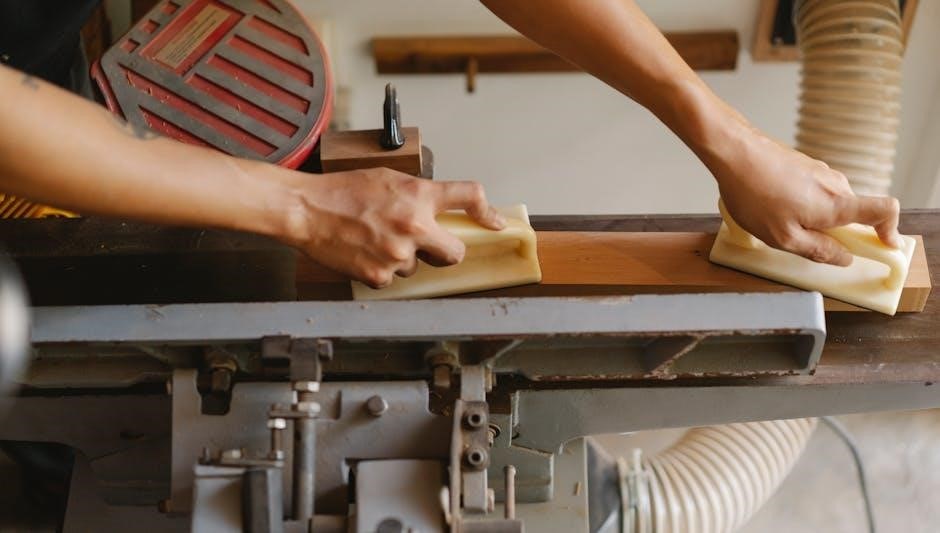
Loading and Unloading Procedures
Proper loading of the Midmark M11 is essential for steam penetration and effective sterilization, as detailed in the operation manual.
Avoid overloading the chamber, ensuring adequate space between items.
When unloading, extreme caution is required as both the processed load and inner surfaces will be hot.
Refer to the manual’s section on “Unloading Hot Trays/Cassettes” to prevent severe burns.
Always use appropriate heat-resistant gloves and tools during the unloading process.
Failure to follow these procedures could result in serious injury.
Unloading Hot Trays/Cassettes
The processed load and the internal surfaces of the Midmark M11 autoclave will be extremely hot after a cycle, as highlighted in the manual.
Always prioritize safety and avoid direct contact to prevent severe burns.
Utilize heat-resistant gloves and appropriate tools – tongs or tray handlers – when removing trays or cassettes.
Exercise caution when opening the door, as steam may still be present.
Ensure a clear path for removing the load to avoid accidental contact or dropping hot items.
Refer to the manual for detailed instructions and safety guidelines.
Understanding the Control Panel
The M11’s control panel facilitates cycle selection and displays critical indicators, as outlined in the operation manual, ensuring precise sterilization control.
Cycle Selection
The Midmark M11 autoclave offers pre-set cycles, with specific temperature, pressure, and time parameters detailed in the manual. These cycles are designed for various load types and sterilization needs.
Understanding these pre-set options is vital for effective sterilization. The manual provides a chart outlining each cycle’s parameters, ensuring operators select the appropriate setting for each load. Proper cycle selection guarantees optimal sterilization results and adherence to safety protocols.
Referencing the manual’s cycle chart is crucial for consistent and reliable performance.
Display Indicators
The Midmark M11’s control panel features several display indicators crucial for monitoring the sterilization process. These indicators provide real-time feedback on cycle status, temperature, pressure, and potential error codes.
The manual details the meaning of each indicator, enabling operators to quickly identify and address any issues. Understanding these signals is essential for safe and effective operation. Pay close attention to indicators signaling cycle completion, door status, and any alarms.
Referencing the manual ensures correct interpretation of all display information.

Maintenance and Cleaning
Regular cleaning, as outlined in the M11 manual, is vital for optimal performance and longevity. Inner surface maintenance prevents buildup and ensures sterilization efficacy.
Regular Cleaning Schedule
Consistent adherence to a cleaning schedule, detailed within the Midmark M11 manual, is paramount for maintaining peak operational efficiency and ensuring consistently sterile results. Daily wiping of exterior surfaces with a mild disinfectant is recommended;
Weekly, a more thorough cleaning of the chamber’s interior should be performed, paying close attention to areas prone to residue accumulation. Monthly, inspect and clean the door gasket to maintain a proper seal. The manual emphasizes the importance of documenting all cleaning activities.
Following the prescribed schedule minimizes the risk of malfunction and extends the autoclave’s lifespan, safeguarding both equipment investment and patient safety.
Inner Surface Maintenance
Maintaining the integrity of the M11 autoclave’s inner surfaces, as outlined in the official manual, is critical for preventing corrosion and ensuring effective sterilization. After each cycle, promptly remove processed loads to avoid prolonged exposure to moisture.
Regularly inspect the chamber walls and trays for any signs of pitting or residue buildup. Utilize approved cleaning agents specifically recommended by Midmark to avoid damaging the stainless steel. The manual details procedures for removing stubborn deposits.
Proper inner surface maintenance extends the autoclave’s lifespan and guarantees consistent, reliable performance, upholding stringent sterilization standards.

Troubleshooting Common Issues
Refer to the service manual (SF-1854) for error code interpretation and addressing steam leaks; these resources aid in diagnosing and resolving M11 issues.
Error Code Interpretation
Decoding error codes is vital for efficient M11 autoclave maintenance, as indicated in the service manual (SF-1854). These codes signal specific malfunctions within the sterilization cycle. Technicians must consult the manual to accurately diagnose the problem, ranging from sensor failures to pressure inconsistencies.
Proper interpretation prevents unnecessary downtime and ensures the autoclave operates safely and effectively. Ignoring error codes can lead to compromised sterilization and potential hazards. The manual provides a comprehensive list, detailing each code’s meaning and suggested corrective actions for Midmark-trained personnel.
Addressing Steam Leaks
Steam leaks in the Midmark M11 autoclave pose a safety risk and compromise sterilization effectiveness. The service manual (SF-1854) guides qualified technicians through leak identification and repair. Common causes include worn gaskets, loose connections, or damaged chamber seals.
Addressing leaks requires careful inspection and replacement of faulty components. Never attempt repairs without proper training. Prioritize safety by disconnecting power before inspection. A thorough leak test, as outlined in the manual, confirms successful repair and ensures the autoclave meets stringent sterilization standards, preventing potential burns from escaping steam.

Service and Repair Information
Qualified Midmark technicians should utilize service manual SF-1854 for M11 repairs. Special tools are required for diagnosis and effective autoclave maintenance.
Special Tools Required
Effective servicing of the Midmark M11 necessitates a specific set of specialized tools, as outlined within the service manual (SF-1854). This table, detailed in the manual, comprehensively lists each tool essential for accurate diagnosis and repair procedures. Technicians must ensure availability of these tools before commencing any service work.
These tools facilitate safe and efficient component access, testing, and replacement, upholding the autoclave’s performance and safety standards. Utilizing non-specified tools could lead to damage or improper functionality, potentially compromising sterilization cycles. Refer to the manual for a complete and updated listing of required tools.
Accessing Service Manuals (SF-1854)
The comprehensive Service Manual (SF-1854), specifically for the M11/D models, is vital for qualified Midmark technicians undertaking service or repair procedures. This manual provides detailed schematics, troubleshooting guides, and component information essential for effective maintenance.
Access to this resource is crucial for ensuring safe and accurate repairs. The Internet Archive hosts a digital copy, offering convenient access alongside official Midmark support channels. Proper utilization of SF-1854 guarantees adherence to Midmark’s standards and maintains the autoclave’s operational integrity.

Technical Specifications
The M11 autoclave operates within defined temperature and pressure ranges, with chamber dimensions detailed in the official manuals for precise load capacity.
Temperature and Pressure Ranges
Understanding the M11’s operational parameters is vital for effective sterilization. The service and installation manuals outline specific temperature and pressure ranges for each pre-set cycle. These parameters, crucial for achieving sterilization goals, are clearly presented in tabular form within the documentation.
Maintaining these ranges ensures proper steam sterilization, eliminating potential risks. Technicians must adhere to these specifications during operation and servicing, referencing the manual for detailed guidance. Deviations can compromise sterilization efficacy and potentially lead to unsafe conditions, highlighting the importance of precise adherence to the documented ranges.
Chamber Dimensions
Accurate knowledge of the M11 autoclave’s chamber dimensions is essential for proper loading and ensuring effective steam penetration. The installation and operation manuals provide detailed specifications regarding the internal width, depth, and height of the sterilization chamber.
These dimensions dictate the maximum size of instruments and cassettes that can be processed in a single cycle. Overloading or improperly arranging items can hinder sterilization. Technicians should consult the manual to optimize loading configurations, maximizing capacity while maintaining sterilization standards. Precise chamber dimensions are critical for safe and efficient operation.

Manual Resources & Locations
Official M11 manuals are readily available on the Midmark website and through the Internet Archive, offering comprehensive support and troubleshooting guides.
Midmark Website Support
Midmark’s official website serves as a primary hub for accessing crucial resources related to the M11 autoclave. Users can find a complete library of documentation, including detailed user manuals for installation and operation.
Furthermore, the website provides access to troubleshooting guides specifically addressing error codes encountered during operation, ensuring efficient problem-solving.
Sterilizer Autoclave Solutions, a dedicated support section, offers expert assistance and answers to frequently asked questions. This centralized platform empowers users to maximize the performance and longevity of their M11 autoclave, ensuring safe and effective sterilization procedures.
Internet Archive Resources
The Internet Archive provides a valuable, freely accessible repository of Midmark M11 autoclave documentation. Users can download or stream the “Midmark M11 UltraClave Installation & Operation Manual” directly, offering a convenient alternative to the official website.
Additionally, the “Midmark M9 M9D M11 M11 D 001 to 019 Service Manual” is available, providing in-depth technical information for qualified technicians.
These resources, categorized under “manuals_medicaldevices,” offer a historical archive and backup source for essential M11 autoclave information, ensuring continued access to vital documentation.

M9/M9D/M11 Compatibility
The M9, M9D, and M11 models share similarities, but operational differences exist; referencing the M11 manual is crucial for correct procedure implementation.
Similarities Between Models
Across the M9, M9D, and M11 Midmark steam sterilizers, a core functionality remains consistent: effective and reliable sterilization of medical instruments. These models all utilize a self-contained steam generation system, eliminating the need for external steam sources.
The fundamental principles of operation – loading, cycle selection, and unloading – are broadly similar, though specific control panel interfaces and cycle parameters may vary. All three models prioritize user safety with features designed to mitigate burn risks associated with steam and hot surfaces.
Furthermore, they share a common focus on providing a validated sterilization process, adhering to industry standards for infection control. Accessing resources like the M11 manual can often provide insights applicable to the other models.
Differences in Operation
While sharing core principles, the M11 demonstrates operational differences from the M9/M9D models. The M11 UltraClave often features an updated control panel interface, potentially offering enhanced cycle customization and monitoring capabilities. Pre-set cycle parameters, detailed in the M11 manual, may include variations in temperature, pressure, and time compared to older models.
Service and repair procedures can also differ, requiring specific tools outlined in the M11/D service manual (SF-1854).
Technicians should always consult the appropriate manual for the specific model being serviced. Understanding these distinctions is crucial for safe and effective operation and maintenance.

Document Revision History
The manual, 003-2707-99, is currently Rev AA3 as of October 11, 2018. These revisions reflect updates to procedures and safety information.
Revision Dates (e.g., 10/11/18)
Document 003-2707-99 underwent revision on October 11, 2018, achieving Revision Number AA3. These dates signify updates to the Midmark M11 autoclave’s operational guidelines and safety protocols.
Tracking these revision dates is vital for ensuring technicians and operators utilize the most current information available. The manual’s evolution reflects ongoing improvements based on field experience and regulatory changes.
Consistent use of the latest revision guarantees adherence to best practices, minimizing risks and maximizing the autoclave’s performance. Referencing the revision history confirms the manual’s validity and accuracy.
Revision Numbers (e.g., Rev AA3)
The M11 autoclave manual, document 003-2707-99, is currently designated as Revision AA3. This alphanumeric code indicates the specific version of the document being used, crucial for accurate procedure adherence.
Revision numbers are essential for identifying updates and changes made to the manual over time. Utilizing a manual with an outdated revision could lead to improper operation or safety concerns.
Always verify the revision number against the latest available documentation from Midmark or reputable sources like the Internet Archive to ensure compliance and optimal performance.